Dual Path Purge Check Valve Diagnostics
Boosted applications that have a lower power-to-weight ratio use two purge flow paths to allow purge under boost conditions in addition to normal vacuum conditions.
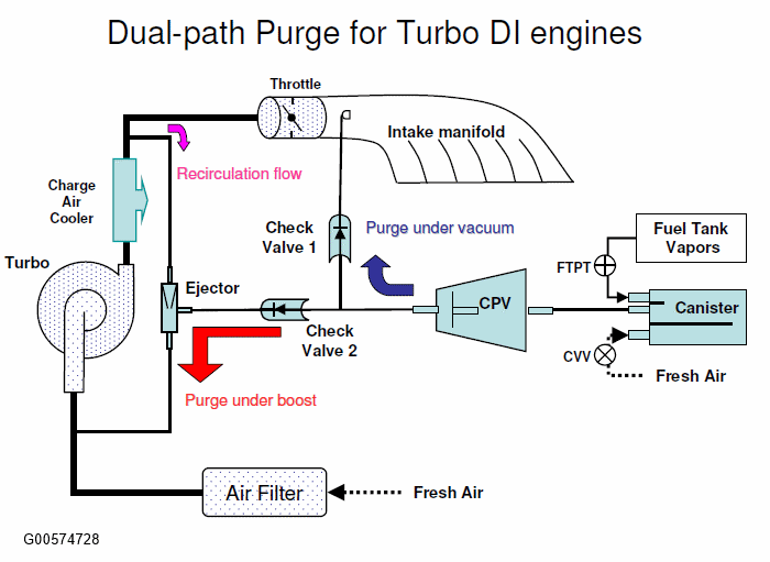
Dual path purge applications use a mechanical check valve 1 (CV1) between the intake manifold and the Canister Purge Valve (CPV). During non-boosted conditions, purge vapors go through check valve 1 before entering the intake. The purpose of this check valve is to prevent reverse flow through the evaporative emissions system under boosted conditions. The check valve is a simple diaphragm type valve were the rubber diaphragm slides inside a cylinder and is pushed against a stop under boost closing off flow through the valve.
A second identical check valve 2 (CV2) is used to facilitate purging during boost. During boosted conditions, a venturi device, called an ejector, is used to generate the needed vacuum for purging. The purge vapors flow through CV2, the turbo charger, and the charge air cooler before entering the intake manifold.
The check valve diagnostic looks for a failed open CV1, a failed closed CV2, a failed ejector, an improperly installed CV1 or CV2, or missing CV1 that could result in intake manifold vapors being pushed back into the evaporative emissions system or lack of purge under boost.
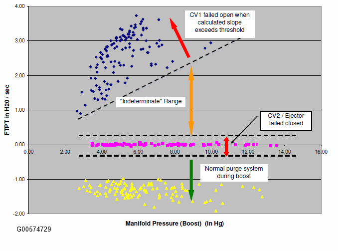
A failed CV1 is detected if the rate of rise in Fuel Tank Pressure Sensor is greater than a calibratable threshold while the Canister Vent Valve is closed, Canister Purge Valve open, and the engine is boosted above a minimum level. Under boost, the system should be sealed if the check valve is operating properly. This condition will set DTC P144C.
A failed CV2 is detected if the rate of change of ejector generated vacuum is relatively flat within a threshold window during boosted conditions. This will set DTC P144C. Steep vacuum slopes for CV2 are indicative of good functioning valves. See the figure below for CV1/CV2 pass and fail ranges.
| DTC | P144C - Evaporative Emission System Purge Check Valve Performance |
| Monitor execution | Once per driving cycle, during boosted operation |
| Monitor Sequence | None |
| Sensors/Components OK | ECT/CHT, IAT, MAP, CPV, CVV, FTPT, FLI, BARO, TIP, WASTEGATE |
| Monitoring Duration | 5 to 10 seconds depending on level of boost |
| Entry Condition | Minimum | Maximum |
| Ambient air temperature | 40 °F | 105 °F |
| Battery Voltage | 11.0 Volts | |
| Fuel level | 15% | 90% |
| Engine Coolant Temperature | 160 °F | |
| Atmospheric Pressure (BARO) | 23" Hg | |
| Boost Pressure (MAP - BARO) | 8" Hg |
| CV1- Pressure Rise Rate (delta pressure / delta time) > 1 " H2
O/sec CV1- Threshold is a function of fuel level with a range of 1.5 to 2.6 CV2- Vacuum Rate (delta vacuum / delta time) >-0.4 and < 0.5 H2 O/sec CV2- Threshold is a function of fuel level with a range of 0.5 to 0.7 for the upper band and -0.4 to -0.3 for the lower band |