Front UEGO Signal
The UEGO sensor infers an air fuel ratio relative to the stoichiometric (chemically balanced) air fuel ratio by balancing the amount of oxygen pumped in or out of a measurement chamber. As the exhaust gasses get richer or leaner, the amount of oxygen that must be pumped in or out to maintain a stoichiometric air fuel ratio in the measurement chamber varies in proportion to the air fuel ratio. By measuring the current required to pump the oxygen in or out, the air fuel ratio (lambda) can be estimated. Note that the measured air fuel ratio is actually the output from the UEGO ASIC pumping current controller and not a signal that comes directly from the sensor.
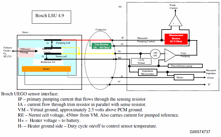
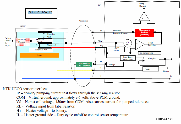
The primary component of a UEGO sensor is the diffusion passage that controls the flow of exhaust gasses into a detection cavity, a Nernst cell (essentially an EGO sensor inside the UEGO sensor) that measures the air fuel ratio in the detection cavity. A control circuitry in the ASIC chip (mounted in the PCM) controls the pumping current (IP) to keep the detection cavity near stoichiometry by holding the Nernst cell at 450 mV. This Nernst cell voltage (RE, VS) is 450mV from the virtual ground (VM, COM), which is approximately 2.5V (Bosch UEGO) or 3.6V (NTK UEGO) above the PCM ground. For the Nernst cell to generate a voltage when the detection cavity is rich, it needs an oxygen differential across the cell. In older UEGO (and HEGO) sensor designs, this was provided by a reference chamber that was connected to outside air through the wire harness that was subject to contamination and "Characteristic Shift Down (CSD)". The new UEGO sensor uses a pumped reference chamber, which is sealed from the outside to eliminate the potential for contamination. The necessary oxygen is supplied by supplying a 20 uA pumping current across the Nernst cell to pump small amounts of oxygen from the detection cavity to the reference chamber. The pumping cell pumps oxygen ions in and out of the detection cavity from and to the exhaust gasses in response to the changes in the Nernst cell voltage. The pumping current flows through the sense resistor and the voltage drop across the sense resistor is measured and amplified. Offset volts are sent out of the ASIC to one of the PCM's A/D inputs. The PCM measures the voltage supplied by the ASIC, determines the pumping current, and converts the pumping current to measured lambda. In general, the circuitry that measures the pumping current is used to estimate the air fuel ratio in the exhaust system.
The UEGO sensor also has a trim (IA) or label resistor (RL). The biggest source of part to part variability in the measured air fuel ratio is difference in the diffusion passage. This source of variation is simply the piece-to-piece differences from the manufacturing process. To compensate for this source of error, each sensor is tested at the factory and a trim or label resistor is installed in the connector. The value of this resistor is chosen to correlate with the measured difference between a particular sensor and a nominal sensor.
For NTK UEGO, the variation in the Ip signal value is corrected for by a compensation coefficient (CC), and then processed by the PCM. The value of CC (Ip rank) is determined by the value of RL. The PCM must command the ASIC to read the value of RL, so CC can be determined. After measuring the value of the label resistor, the PCM software will multiply the measured pumping current (Ip) by a compensation coefficient and determine a corrected pumping current that is used to calculate the measured exhaust air fuel ratio. During each power up, the PCM will briefly turn the UEGO heater power off, measure the output voltage from the voltage divider several times, average it, and estimate the resistance of the label resistor. The PCM will do this estimation multiple times, and if all samples are consistently within one resistor "rank", then the RL compensation coefficient determination is completed and the resistor "rank" compensation coefficient value will be stored in keep alive memory. On the other hand, if the several readings are not consistently within one rank for some amount of time, then the PCM A/D input is considered not reliable/RL erratic, and a trim circuit erratic malfunction (P164A, P164B) will be set. Conversely, if the estimated resistance is too high, then the software in the PCM will indicate RL circuit shorted to ground or open, and a trim circuit low malfunction (P2627, P2630) will be set. If the estimated resistance is too low, then the software will indicate RL circuit shorted to power, and a trim circuit high malfunction (P2628, P2631) will be set. Once a trim circuit malfunction is detected, then the compensation coefficient of the label resistor "rank" stored in KAM will be used.
For Bosch UEGO, the trim resistor is connected in parallel to the pumping current sense resistor and the pumping current flows through both. The trim resistor adjusts the measured pumping current back to the expected nominal value at any given air fuel ratio (correcting for the sensor to sensor variations in the diffusion passage). Small trim resistors are required for sensors that require more pumping current at any particular lambda. Conversely, for sensors with lower diffusion rates than average, less pumping current is required, so a higher than average impedance trim resistor is installed. When IA circuit is open, all of the pumping current flows through the measuring resistor which increases the measured voltage. Since the pumping current is amplified, the UEGO pumping current to lambda transfer function will reflect the error. The slope of the UEGO sensor transfer function changes, which results in the wrong output of the UEGO signal (the slope of the pumping current to lambda relationship can increase or decrease). For "stoichiometric" air/fuel control applications, an open IA circuit is not monitored since the lambda error is minimal in "stoichiometric" mode. A worst case (40 ohm resistor) open IA was tested on a 2008 MY 3.5L Taurus PZEV and showed no impact on tailpipe emissions.
The time spent at the limits of the short term fuel trim is monitored after vehicle startup when closed loop fuel has been requested, during closed loop fuel conditions, or when open loop fuel has been requested due to UEGO sensor fault. Excessive time with short term fuel trim at its limits (up to +/- 40%), or no rich / lean activity seen since startup indicates a "lack of switch" malfunction. Since "lack of switching" malfunctions can be caused by UEGO sensor malfunctions or by shifts in the fuel system, DTCs are stored that provide additional information for the "lack of switching" malfunction. Different DTCs indicate whether the sensor always indicates lean (P2195, P2197), or always indicates rich (P2196, P2198).
| DTCs | P2195 - Lack of switching, sensor indicates lean, Bank 1 P2196 - Lack of switching, sensor indicates rich, Bank 1 P2197 - Lack of switching, sensor indicates lean, Bank 2 P2198 - Lack of switching, sensor indicates rich, Bank 2 |
| Monitor Execution | continuous, from startup and while in closed loop fuel or open loop fuel due to UEGO sensor fault |
| Monitor Sequence | None |
| Sensor OK | ECT, IAT, MAF, MAP, VSS, TP, ETC, FRP, FVR, DPFE EGR, VCT, VMV/EVMV, CVS, CPV, EVAPSV, FTP, CKP, CMP, ignition coils, injectors, no misfire DTCs, no system failures affecting fuel, no EVAP gross leak failure, UEGO heaters OK, no "lack of movement" malfunction, no UEGO circuit malfunction |
| Monitoring Duration | 30 seconds to register a malfunction |
| Entry Condition | Minimum | Maximum |
| Closed Loop or Open Loop Requested due to UEGO sensor fault | ||
| No fuel flow entering thru PCV during cold start when flashing off fuel in oil (for O2 Sensor Stuck Rich DTCs only) | ||
| Inferred Ambient Temperature | -40 °F | |
| Time within entry conditions | 10 seconds | |
| Fuel Tank Pressure | 10 in H2 0 | |
| Fuel Level | 15% | |
| UEGO ASIC not in recalibration mode | ||
| No air passing through during valve overlap (scavenging). | ||
| Battery Voltage | 11.0 Volts | 18.0 Volts |
| Stage 1: > 30 seconds since reaching the short term fuel trim limits while closed loop fuel. Stage 2: < 0.5 seconds rich or < 0.5 seconds lean since startup for > 30 seconds in test conditions while open loop fuel is requested due to UEGO sensor fault. |
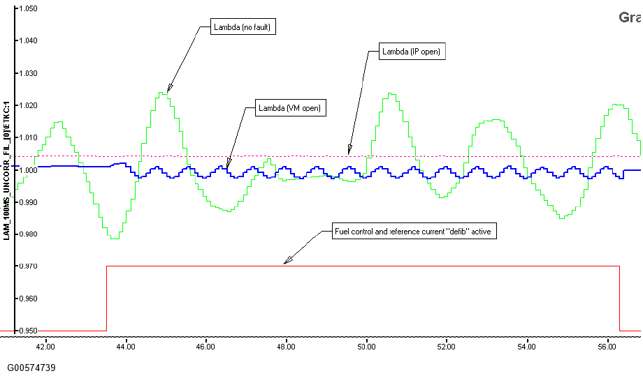
The time spent when the measured lambda is nearly 1.0 is also monitored on Bosch UEGO applications using Bosch CJ125 or Conti-Siemens ATIC42 ASIC. The monitoring is conducted after vehicle startup when closed loop fuel has been requested, during closed loop fuel conditions, or when open loop fuel has been requested due to UEGO sensor fault. Excessive time without measured lambda deviating from 1.0, in spite of attempts to force activity (via fuel control and reference current "defib") in the measured lambda, will indicate either a "lack of movement - open Pump Current circuit" malfunction or a "lack of movement - open Reference Ground circuit" malfunction. An open Pump Current circuit (IP) is differentiated from an open Reference Ground circuit (VM) by measuring the movements in the measured lambda during the reference current defib. Change in lambda movement below a minimum threshold indicates "lack of movement- open Pump Current circuit" malfunction, which results in P2237, P2240 DTCs (replaced P0134/P0154 DTCs). Conversely, change in lambda movement greater than the minimum threshold indicates an open VM, which results in P2251, P2254 DTCs (replaced P0130/P0150 DTCs). Note that the open VM detection via reference current defib is new in 2011 MY applications.
Since the Bosch CJ125 or the Conti-Siemens ATIC42 ASIC do not have the capability to specifically detect an open RE or VM, separate diagnostics were created to monitor these failures. An open RE or VM will typically cause the impedance of the Nernst cell to increase. An open RE will cause the UEGO voltage to be greater than or less than a malfunction threshold while an open VM will cause the UEGO voltage to be within a malfunction band. Note that this open VM detection will only enable if the UEGO is unable to control the heater voltage at the desired set point; otherwise, the "lack of movement- open Reference Ground circuit" diagnostic will enable.
| DTCs | P2243 - O2 Sensor Reference Voltage Circuit/Open (Bank 1, Sensor 1). (replaces P0130) P2247 - O2 Sensor Reference Voltage Circuit/Open (Bank 2, Sensor 1). (replaces P0150) P2251 - O2 Sensor Negative Current Control Circuit/Open (Bank 1, Sensor 1) (replaces P0130) P2254 - O2 Sensor Negative Current Control Circuit/Open (Bank 2, Sensor 1) (replaces P0150) |
| Monitor execution | continuous |
| Monitor Sequence | Intrusive Stream 1 UEGO heater current monitor completed |
| Sensors OK | UEGO heaters OK, no UEGO circuit malfunction |
| Monitoring Duration | 10 seconds to register a malfunction |
| Entry Condition | Minimum | Maximum |
| UEGO ASIC not in recalibration mode | ||
| All injectors on (no Decel Fuel Shut Off) | ||
| Short term fuel trim | 33% | |
| Time heater control voltage at maximum limit during open loop heater control | 9 seconds (Bosch UEGO) 20 seconds (NTK UEGO) |
|
| Time heater control voltage at maximum or minimum limit during closed loop heater control | 7 seconds (Bosch UEGO) 1 second (NTK UEGO) |
|
| Battery Voltage | 11.0 Volts | 18.0 Volts |
| Open RE circuit: UEGO voltage: > 4.7 V or < 0.2 V for 10 seconds to set a DTC. Open VM circuit: 1.45 V < UEGO voltage < 1.55 V for 10 seconds to set a DTC (Bosch CJ125). 1.95 V < UEGO voltage < 2.05 V for 10 seconds to set a DTC (Conti-Siemens ATIC42). |
| DTCs | P2237 - O2 Sensor Positive Current Control Circuit/Open (Bank 1, Sensor 1) (replaces P0134) P2240 - O2 Sensor Positive Current Control Circuit/Open (Bank 2, Sensor 1) (replaces P0154) |
| Monitor execution | continuous, from startup and while in closed loop fuel or open loop fuel due to UEGO sensor fault |
| Monitor Sequence | None |
| Sensors OK | ignition coils, injectors, no misfire DTCs, no system failures affecting fuel, UEGO heaters OK, no "lack of switching" malfunction, no "lack of movement open reference ground circuit" malfunction, no UEGO circuit malfunction |
| Monitoring Duration | 10 - 20 seconds to register a malfunction |
| Entry Condition | Minimum | Maximum |
| Closed Loop or Open Loop Requested due to UEGO sensor fault | ||
| Constant lambda near stoich (~1) | 0.99 | 1.01 |
| Time since no lambda activity seen since start up | 30 sec | |
| Time since no lambda activity during intrusive Stream 1 response monitor | 3 sec | |
| Inferred Ambient Temperature | -40 °F | |
| Injector fuel pulse width | 650 usec | |
| UEGO ASIC not in recalibration mode | ||
| No air passing through during valve overlap (scavenging). | ||
| Battery Voltage | 11.0 Volts | 18.0 Volts |
| Stage 1: > 20 seconds in test conditions without lambda movement during fuel control and reference current "defib" while in closed loop fuel and < = 0.05 change in lambda movement. Stage 2: < 0.2 seconds without lambda movement since startup for > 30 seconds in test conditions during reference current "defib" while open loop fuel is requested due to UEGO sensor fault and < = 0.05 change in lambda movement. |
| DTCs | P2251 - O2 Sensor Negative Current Control Circuit/Open (Bank 1, Sensor 1) (replaces P0130) P2254 - O2 Sensor Negative Current Control Circuit/Open (Bank 2, Sensor 1) (replaces P0150) |
| Monitor execution | continuous, from startup and while in closed loop fuel or open loop fuel due to UEGO sensor fault |
| Monitor Sequence | None |
| Sensors OK | ignition coils, injectors, no misfire DTCs, no system failures affecting fuel, UEGO heaters OK, no "lack of switching" malfunction, no "lack of movement open pump current circuit" malfunction, no UEGO circuit malfunction |
| Monitoring Duration | 10 - 20 seconds to register a malfunction |
| Entry Condition | Minimum | Maximum |
| Closed Loop or Open Loop Requested due to UEGO sensor fault | ||
| Constant lambda near stoich (~1) | 0.99 | 1.01 |
| Time since no lambda activity seen since start up | 30 sec | |
| Time since no lambda activity during intrusive Stream 1 response monitor | 3 sec | |
| Injector fuel pulse width | 650 usec | |
| UEGO ASIC not in recalibration mode | ||
| No air passing through during valve overlap (scavenging). | ||
| Battery Voltage | 11.0 Volts | 18.0 Volts |
| Stage 1: > 20 seconds in test conditions without lambda movement during fuel control and reference current "defib" while in closed loop fuel and > 0.05 change in lambda movement. Stage 2: > 20 seconds in test conditions without lambda movement during reference current "defib" while open loop fuel is requested due to UEGO sensor fault and > 0.05 change in lambda movement. |
UEGO equipped vehicles monitor the circuitry between the PCM and the UEGO sensor via the wire diagnostics capability included on the UEGO ASIC chip. The wire diagnostics will detect wires (IP, IA, VM/COM, RE/VS) shorted to battery, or ground, and in most cases will detect open circuits (IP, VM/COM, RE/VS). In particular, the NTK TIF0003 and Conti ATIC142 ASIC chips can do open circuit diagnostics. Beginning 2015 MY, applications using Conti ATIC142 ASIC can also detect open IA fault via the wire diagnostics capability included on the ASIC.
The diagnostic bits are transmitted to the PCM via SPI (serial peripheral interface). The SPI communication is validated continuously, and if a SPI communication failure is detected, fault code(s) P064D and/or P064E will be set. The ASIC is also capable of detecting internal circuitry failure; in which case, an ASIC failure DTC (P1646, P1647) along with the SPI communication failure DTC (P064D, P064E) will be set.
- Beginning 2011 MY, the general UEGO circuit diagnostic DTCs P0130/P0150, are now replaced by more specific DTCs.
- A shorted to ground circuit (Bosch UEGO - IP, IA, RE, VM; NTK UEGO - IP, VS, COM) will set P0131/P0151 DTCs.
- A shorted to battery circuit (Bosch UEGO - IP, IA, RE, VM; NTK UEGO - IP, VS, COM) will set P0132/P0152 DTCs.
- An open Pump Current circuit (IP) will set P2237/P2240 DTCs.
- An open Reference Ground circuit (VM/COM) will set P2251/P2254 DTCs.
- An open Reference Voltage circuit (RE/VS) will set P2243/P2247 DTCs.
| DTCs | P0131
- O2 Sensor Circuit Low Voltage (Bank 1, Sensor 1). (Note: Sets for short to ground on Bosch UEGO- IP, IA, RE, VM; NTK UEGO - IP, VS, COM. Replaces P0130 in Bosch UEGO applications.) P0151 - O2 Sensor Circuit Low Voltage (Bank 2, Sensor 1). (Note: Sets for short to ground on Bosch UEGO- IP, IA, RE, VM; NTK UEGO - IP, VS, COM. Replaces P0150 in Bosch UEGO applications.) P0132 - O2 Sensor Circuit High Voltage (Bank 1, Sensor 1). (Note: Sets for short to battery on Bosch UEGO- IP, IA, RE, VM; NTK UEGO - IP, VS, COM. Replaces P0130 in Bosch UEGO applications.) P0152 - O2 Sensor Circuit High Voltage (Bank 2, Sensor 1). (Note: Sets for short to battery on Bosch UEGO- IP, IA, RE, VM; NTK UEGO - IP, VS, COM. Replaces P0150 in Bosch UEGO applications. P2237 - O2 Sensor Positive Current Control Circuit/Open (Bank 1, Sensor 1). (Note: This DTC sets for open IP. Replaces P0130 in NTK UEGO applications. P2240 - O2 Sensor Positive Current Control Circuit/Open (Bank 2, Sensor 1). (Note: Sets for open IP. Replaces P0150 in NTK UEGO applications). P2243 - O2 Sensor Reference Voltage Circuit/Open (Bank 1, Sensor 1). (Note: Sets for open VS. Replaces P0130 in NTK UEGO applications). P2247 - O2 Sensor Reference Voltage Circuit/Open (Bank 2, Sensor 1). (Note: Sets for open VS. Replaces P0150 in NTK UEGO applications). P2251 - O2 Sensor Negative Current Control Circuit/Open (Bank 1, Sensor 1). (Note: Sets for open COM. Replaces P0130 in NTK UEGO applications). P2254 - O2 Sensor Negative Current Control Circuit/Open (Bank 2, Sensor 1). (Note: Sets for open COM. Replaces P0150 in NTK UEGO applications). P164A - O2 Sensor Positive Current Trim Circuit Performance (Bank 1, Sensor 1). (Note: Sets for an erratic RL in NTK UEGO applications only). P164B - O2 Sensor Positive Current Trim Circuit Performance (Bank 2, Sensor 1). (Note: Sets for an erratic RL in NTK UEGO applications only). P2626 - O2 Sensor Positive Current Trim Circuit Open (Bank 1, Sensor 1) P2629 - O2 Sensor Positive Current Trim Circuit Open (Bank 2, Sensor 1) P2627 - O2 Sensor Positive Current Trim Circuit Low (Bank 1, Sensor 1). (Note: Sets for open or short to ground RL in NTK UEGO applications only). P2630 - O2 Sensor Positive Current Trim Circuit Low (Bank 2, Sensor 1). (Note: Sets for open or short to ground RL in NTK UEGO applications only). P2628 - O2 Sensor Positive Current Trim Circuit High (Bank 1, Sensor 1). (Note: Sets for short to battery RL in NTK UEGO applications only). P2631 - O2 Sensor Positive Current Trim Circuit High (Bank 2, Sensor 1). (Note: Sets for short to battery RL in NTK UEGO applications only). P1646 - Linear O2 Sensor Control Chip, Bank 1. P1647 - Linear O2 Sensor Control Chip, Bank 2. P064D - Internal Control Module O2 Sensor Processor Performance (Bank 1). P064E - Internal Control Module O2 Sensor Processor Performance (Bank 2). |
| Monitor execution | continuous |
| Monitor Sequence | None |
| Sensors OK | UEGO heaters OK |
| Monitoring Duration | 10 seconds to register a malfunction |
| Entry Condition | Minimum | Maximum |
| Fault reported by UEGO ASIC | ||
| Battery Voltage | 11.0 Volts | 18.0 Volts |
| UEGO ASIC indicated malfunction, DTC sets after 10 seconds when circuit failure is present. |
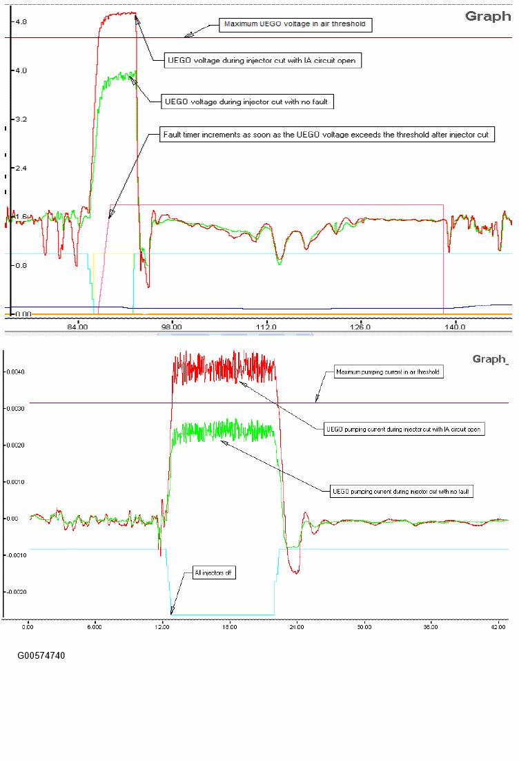
For "Non-Stoichiometric Closed Loop (NSCL)" air/fuel control applications, a continuous open IA diagnostic is required since the lambda error is more significant in this mode. For UEGO ASICs that do not have capability to detect open IA, a separate continuous open IA diagnostic (Air Rationality Test) is created to monitor the open IA circuit fault. This diagnostic will always monitor the UEGO sensor voltage or pumping current reading during Decel Fuel Shut Off (DFSO) event. The monitor compares the UEGO sensor voltage or pumping current reading in air against the expected value for pure air. If the UEGO sensor voltage or pumping current during DFSO exceeds the maximum UEGO voltage/pumping current in air threshold, then the fault timer increments. If the fault timer exceeds the fault time threshold, then open IA DTC P2626 and/or P2629 will set. Since transient sources of fuel in the exhaust after injector cut can contribute to the UEGO sensor voltage/pumping current to read lower (rich), the air rationality monitor will not call a pass until the transient sources of fuel have been exhausted and pure air entry conditions during DFSO are met (i.e. all injectors must be off, purge must be off, no fuel must be leaking around the PCV valve, and a few transport delays must have passed to allow the last fuel transients to be exhausted leaving nothing for the sensor to see, but air). Note: Beginning 2011 MY and beyond, this diagnostics will monitor the UEGO pumping current against the expected value for pure air instead of the UEGO voltage so the monitor can be ASIC chip independent.
| DTCs | P2626 - O2 Sensor Positive Current Trim Circuit Open (Bank 1, Sensor 1) P2629 - O2 Sensor Positive Current Trim Circuit Open (Bank 2, Sensor 1) |
| Monitor execution | continuous, every DFSO event |
| Monitor Sequence | Stream 1 UEGO heater voltage check completed, > 30 seconds time in lack of movement test, > 30 seconds time in lack of switch test |
| Sensors OK | FTP, injectors, UEGO heaters OK, no "lack of switching" malfunction, no "lack of movement" malfunction, no purge system failure, no UEGO circuit malfunction, no UEGO FAOS monitor malfunction, no front UEGO response rate malfunction |
| Monitoring Duration | 2 seconds to register a malfunction |
| Entry Condition | Minimum | Maximum |
| No injectors stuck open | ||
| No purge system failure | ||
| Fuel Tank Pressure | 10 in H2O | |
| Closed pedal | ||
| DFSO entry conditions met | ||
| DFSO requested | ||
| DFSO injectors cut | ||
| No purge flow being requested (pass criteria only) | ||
| No fuel flow entering thru PCV during cold start when flashing off fuel in oil (pass criteria only) | ||
| Transport delay (pass criteria only) | 2 sec | |
| UEGO ASIC not in recalibration mode | ||
| Battery Voltage | 11.0 Volts | 18.0 Volts |
| UEGO voltage
: > 4.55 V (max UEGO sensor voltage in air, normal range) or > 3.0 V (max UEGO sensor voltage in air, wide range) for >= 2 seconds in test conditions. UEGO pumping current: > 0.00309 Amps for >= 2 seconds in test conditions. |