Rear Ho2S DECEL Fuel Shut Off Response Test (2009 My+)
The catalyst monitor tracks and uses the length of the rear HO2S signal. The rear HO2S is also known as the Catalyst Monitor Sensor (CMS). As the catalyst ages, air/fuel fluctuations begin to break through the catalyst and the length of this signal increases. Eventually the length of the CMS signal becomes long enough to identify a failure for the catalyst monitor.
When an HO2S sensor degrades, it's response to air/fuel fluctuations slows down. The effect of a slow rear HO2S sensor on the catalyst monitor is to reduce the length of the signal. A slow CMS sensor, therefore, may cause the catalyst monitor to incorrectly pass a failed catalyst. The purpose of the Rear DFSO Response diagnostic is to ensure the catalyst monitor has a valid CMS sensor with which to perform the catalyst monitor diagnostic. The monitor is set to trigger at the level of degradation that will cause the catalyst monitor to falsely pass a malfunction threshold catalyst.
The OBD-II regulations require this monitor to utilize Decel Fuel Shut Off (DFSO). Ford plans to aggressively use DFSO starting in the 2009 MY on many applications to improve fuel economy. The DFSO rear O2 response test will be phased in coincident with this feature.
The main part of the test is the measured rich to lean response rate. It is determined by a "slew" rate calculation which determines the rich to lean slope of the sensor during a Decel Fuel Shut Off (DFSO) event which occurs during closed pedal at vehicle speeds higher than 28 mph. The calculation for the slew rate (mV/sec) is illustrated below.
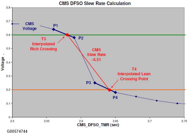
Linear interpolation is performed to calculate the Slew Rate.
- For 2010 MY and earlier, interpolate between points P1 and P2 to determine the time at which the rich limit threshold of 0.6 volts was crossed. For 2011MY and beyond, capture the time at T3 at which the rich limit threshold of 0.6 volts was crossed.
- For 2010 MY and earlier, interpolate between points P3 and P4 to determine the time at which the lean limit threshold of 0.2 volts was crossed. For 2011MY and beyond, capture the time at T4 at which the lean limit threshold of 0.2 volts was crossed.
- Use the times and the thresholds to calculate the slope or "slew rate" of the CMS sensor from 0.6 to 0.2 volts.
Diagnostic Data Acquisition Event Plot is a schematic of what happens when the pedal is closed and the engine enters DFSO.
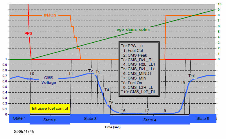
The top half of the graph shows the following signals:
- Closed pedal timer (ego_dcms_cptmr).
- PPS (Pedal Position Sensor)
- INJON (# of fuel injectors turned on)
The bottom half of the graph shows a CMS signal with black lines and a "Tx" number representing all of the points of interest where the monitor captures data.
The monitor measures the CMS Rich to Lean slew rate during a DFSO event. The CMS voltage must be rich prior to the injector cut for a valid measurement event. Each fuel cut can only yield 1 valid event. The monitor will complete after 3 valid events. Additional valid event results will be stored and applied over the next drive cycle if necessary for monitor completion.
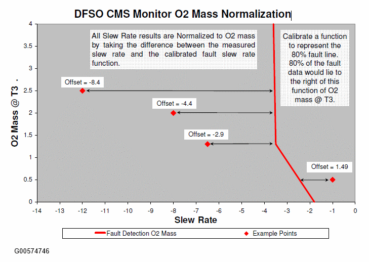
The slope or slew rate of the CMS sensor going from rich to lean is a negative number with the units of mVolts/sec. The measured slew rate changes as an O2 sensor degrades, but it will also change as a function of catalyst oxygen storage/age; therefore, the slew rate is normalized using an offset based on catalyst oxygen storage/age. The catalyst oxygen storage/age is calculated by integrating the level of oxygen mass in the exhaust stream from the time the injectors turn off to the time where the slew rate calculation begins. The fault line (red line in the chart below) is calibrated to 80% of the fault distribution for various levels of oxygen storage/catalyst age. As shown below, the integrated oxygen mass becomes smaller with catalyst age.
The final output of the monitor = the measured slew rate - normalized fault line, therefore, any positive number will represent a fault. For the step change logic the fault threshold will represent 50% of the failed distribution (~ 0.3).
The delayed response part of the test indicates that the sensor is stuck in range. The code sets if the sensor can't get above a calibrated rich or lean voltage prior to a calibrated time out period. This time out must happen three times in a row to set the fault. If it happens once or twice and then the response monitor completes, the counter will be reset and the sensor will have to fail 3 times in a row to again set the DTC.
Due to the fact that intrusively driving the CMS sensor rich will cause driveability and emission concerns, there are other several condition counters that have to fail prior to intrusively forcing the sensor to go rich. The sequence of events to get to the rich failure is shown below:
- Initially, in order to avoid excess emissions, the monitor will only run if the CMS voltage is rich (> 0.6 volts) or CMS sensor is transitioning from lean to rich (large positive slope. 0.2).
- Successive failures are counted up; when the count exceeds 5 to 10 failures the monitor will now intrusively force rich fuel to run the test.
- In order to avoid a driveability issues as a result of a lean shifted bank, the first phase of intrusive control has a short time out (1 to 2 seconds).
- Successive failures are counted up; when the count exceeds 3 failures the monitor will now intrusively force rich fuel to failure or a rich sensor.
- All controllable measures have failed to force the sensor to switch, so the strategy will drive rich until the sensor switches or the failure time out is exceeded (5 to 10 seconds).
- Successive failures are counted up; when the count exceeds 3 failures the monitor will now set a fault (P013E for bank 1 or P014A for bank 2).
If the sensor is stuck rich (can't get lean) the fault procedure is:
- While the injectors remain off, the sensor must get lean (<0.1 volts) prior to the failure time which must be set to account for a green catalyst (5 to 10 seconds).
- Successive failures are counted up; when the count exceeds 3 failures the monitor will now set a fault (P013E for bank 1 or P014A for bank 2).