Transmission Inputs
Transmission Range Sensor - 6F35 uses a Non-contacting Pulse Width Modulated Transmission Range Sensor (TRS) that provides a duty cycle signal for each position. This signal is transmitted at a frequency of 125 Hz. The PCM decodes the duty cycle to determine the driver-selected gear position (Park, Rev, Neutral, OD, 3, 2, 1). This input device is checked for out of range frequency, low duty cycle and high duty cycle input signals. (P0706, P0707, P0708)
Select Shift Transmission (SST) Up/Down
6F35 is picking up SST for 10 MY. This system has two new PCM inputs, an upshift switch and a downshift switch. The switches are built into the shifter (defined as an H-gate in this implementation):
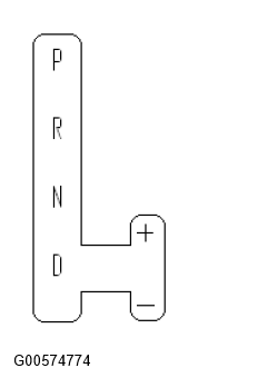
Both PCM inputs are open when the shifter is on the left hand side. From Drive as the customer moves the shifter to the right both inputs transition from open to closed (the TRS continues to indicate Drive). The control system enters "Grade Assist Mode" (provides more engine braking but still follows an automatic shift schedule) at this point. If the customer never requests a shift the control system will remain in Grade Assist Mode.
The customer requests a shift by pushing the shifter up or down, which opens the appropriate switch. Once the customer requests a shift the control system transitions from Grade Assist Mode to SST. In SST the control system follows the customer's commands except for special conditions (downshifts to the lowest available gear at high pedal, downshifts at low speeds).
Diagnostics monitors for either switch closed in Park, Reverse or Neutral, and a failure will result in non-MIL P0815 (upshift switch error) or P0816 (downshift switch error) fault codes.
If either switch fails open the customer will not be able to enter Grade Mode or SST since both switches must transition from open to closed while in the Drive position to enter SST.
If either switch is detected failed Grade Assist Mode and SST are disabled and the control system defaults to Drive (normal automatic shift schedules).
Paddles:
The right paddle controls upshifts, the left paddle controls downshifts. Pulling on the appropriate paddle changes the state of the digital input.
In S the transmission will automatically shift until one of the paddles is actuated, then it will switch into "Select Shift Transmission" (SST), holding the customer selected gear until a shift request is made via the paddles, with some minor overrides like the transmission will downshift from 5th or 6th to 1st at a stop to avoid launching in a high gear if the customer forgot to downshift upon coming to a stop.
In Drive the paddles can be used to temporarily select a gear - this feature is called "Live in Drive". The system will hold the customer selected gear indefinitely under certain operating conditions (closed pedal going down a grade or in an turn), but under normal road load conditions the system will time out after 2-3 seconds, returning to the normal automatic shift schedules.
The paddles are ignored in P, R and N.
Speed Sensors
The Turbine Shaft Speed (TSS) sensor and Output Shaft Speed (OSS) sensor are Hall Effect inputs that are checked for rationality. The vehicle speed signal is provided from the ABS system (if present) to the PCM, or is derived from OSS. If the engine rpm is above the torque converter stall speed and engine load is high, it can be inferred that the vehicle must be moving. If there is insufficient output from the TSS sensor, a malfunction is indicated (P0715). If there is insufficient output from the OSS sensor, a malfunction is indicated (P0720). 6F35 applications currently use ABS vehicle speed the primary source of vehicle speed with OSS as a backup, if both sources are failed a P1934 "Vehicle Speed Signal" DTC is stored.
Transmission Fluid Temperature
6F35 has a feature called "Cold mode" (1st implemented in 5R110W in 2003 MY). If TFT is below -20 deg F, the transmission will limit operation to 1st, 2nd, 3rd, and 4th gears (5th and 6th gears are disabled). Cold mode remains in effect until TFT rises above -20 deg F or vehicle operation (based on shift times or heat generated by driving) indicates that TFT should not be in the cold mode range, at which point normal operation is enabled.
if TFT is failed at start up the transmission will be placed in cold mode and remain there until TFT is no longer failed and above -20 deg F or the vehicle operating conditions listed above trigger an exit from cold mode.
Once out of cold mode a TFT failure will not trigger cold mode (can only go into cold mode once/power-up); this mode is the same as implemented on 5R110W in 2003.5 MY.
TFT is monitored for circuit faults (P0712, P0713) and in-range failures (P0711)
For this reason all TFT diagnostics illuminate the MIL on 6F35.