Driveline System - General Information
Overview
Driveline System
The driveline system consists of the following components:
- Center support bearing
- Driveshaft assembly
- Front halfshafts
- Rear halfshafts
- ATC / rear axle
FWD vehicles, the transaxle transmits power from the engine to the halfshafts.
AWD vehicles, power is transmitted from the engine through the transaxle to the PTU. The PTU transfers engine power from the transaxle to the front halfshafts, and through the driveshafts to the ATC / rear axle and halfshafts. REFER to Transfer Case - Power Transfer Unit (PTU) .
The engine angle is built into the engine mounts. If the engine angle is out of specification, the engine mounts must be inspected for damage.
Vehicle Certification (VC) Label Example
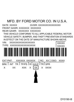
The VC label is located in the driver door jamb. The axle code is on the VC label.
The axle ratio is 2.93 and the ring gear has a diameter of 174 mm (6.8504 in).
The wheel speed sensor rings for FWD vehicles are located on the front halfshafts and are mounted to the rear inner spindles.
The wheel speed sensor rings are located on the front and rear halfshafts for AWD vehicles.
Driveshaft
The driveshaft is a 2-piece shaft with a rubber isolated center bearing.
The driveshaft is a balanced assembly and has traditional balance weights attached (spot welded) by the manufacturer.
U-Joint
The CV and UHSS U-joint are installed new with the driveshaft.
The front and rear CV joints are:
- lubricated with a special lubricant and require no additional lubrication.
- not serviceable
The center U-Joint are:
- a lubed for life design that requires no periodic lubrication.
- equipped with nylon thrust washers located at the base of each bearing cup which control end play, position the needle bearings and improve grease movement.
- not serviceable
RDU
The ATC RDU is serviced as an assembly.
The RDU housing cover uses a silicone sealant rather than a gasket.
Each halfshaft is held in the RDU case by a driveshaft bearing retainer circlip that is located on the inner CV joint stub shaft pilot bearing housing. When each halfshaft is installed, the driveshaft bearing retainer circlip engages a slot in the RDU side gear.
The RDU operates as follows:
- The RDU pinion receives power from the engine through the transaxle, PTU, driveshaft ATC, and is always engaged.
- The pinion gear rotates the ring gear, which is bolted to the differential case outer flange.
- Inside the differential case, 2 differential pinion gears are mounted on a differential pinion shaft that is pinned to the differential case.
- These differential pinion gears are engaged with the differential side gears, to which the halfshafts are splined.
- As the differential case turns, it rotates the halfshafts and rear wheels.
- When it is necessary for one wheel and halfshaft to rotate faster than the other, the faster turning differential side gear causes the differential pinion gears to roll on the slower turning differential side gear. This allows differential action between the 2 halfshafts.
Halfshafts
The drive halfshafts consist of the following components:
- Inner CV joints
- Outer CV joints
- CV joint boot clamps
- CV joint boots
- Tripod joint housings
- Retainer circlips
- Front intermediate shaft bearing
- Vehicles equipped with a 3.5L GDTI, the RH halfshaft is serviced separate from the intermediate shaft
The front intermediate shaft bearing is pressed on and is only serviced as an assembly with the intermediate shaft.
- The inner and outer CV joints connect to a splined shaft. A circlip holds the cross groove inner race assembly (inner CV joint) together.
- A circlip retains the splined inner CV joint. Install a new axle circlip each time the halfshaft is removed from the vehicle.
- Vehicles equipped with a 3.5L GDTI, a circlip holds the RH halfshaft to the intermediate shaft.
- A wheel hub nut secures the side shaft assembly (interconnecting shaft and outer CV joint) to the wheel hub. Install a new wheel hub nut each time the halfshaft is removed from the vehicle.
Halfshaft Handling
Handle all halfshaft components carefully during removal and installation procedures. Never use a hammer to remove or install the halfshafts. Never use the halfshaft assembly as a lever to position other components. Always support the free end of the halfshaft. Do not allow the boots to contact sharp edges or hot exhaust components. Do not drop assembled halfshafts. The impact may cut the boots from the inside without evidence of external damage. When disconnecting the lower ball joint, do not allow the stud to impact the halfshaft as this may damage the CV joint bolt seal.