PINPOINT TEST H : The Power Seat is Inoperative, Does Not Operate Correctly - Both Rear
- H1 CONFIRM THE PRELIMINARY INSPECTION HAS BEEN COMPLETED
- Perform the steps outlined in the Preliminary Inspection. Refer to Seating .
Does either seat move to any position?
Yes If both seats operate to each selected position correctly, GO to H2. If only the LH seat does not operate correctly, GO to Pinpoint Test A . If only the RH seat does not operate correctly, GO to Pinpoint Test B . If both seats move but neither seat correctly obtains all the selected positions, GO to H20. No GO to H3. - H2 CHECK THE OPERATION OF EACH SEAT SEPARATELY
- Check the seats.
- Select LH using the seat select button and operate the seat to each position (NORMAL, STOW and FOLD), allowing the seat to complete each selection.
- Select RH using the seat select button and operate the seat to each position, allowing the seat to complete each selection.
Do both seats operate correctly?
Yes The system is operating correctly at this time. CHECK for causes of an intermittent concern such as loose, corroded or disconnected connectors or pinched or damaged wiring and REPAIR as necessary. No GO to H14. - H3 CHECK THE BCM FOR DTCs
- Ignition ON.
- Using a scan tool, perform BCM self-test.
Are DTCs present?
Yes For DTC B1317:15, GO to H10. For DTC B1317:11, GO to H12. For any other DTCs, REFER to Multifunction Electronic Modules . No GO to H4. - H4 CHECK FOR VOLTAGE AND GROUND TO THE PFSM
- Disconnect: PFSM C4250A
.
- To access the PFSM, Refer to Power-Fold Seat Module (PFSM) .
- Verify the vehicle is in PARK and the liftgate is open.
- Verify the courtesy lights are on. If needed, close and open any door on the vehicle.
Is the voltage greater than 11 volts?
Yes GO to H13. No GO to H5. - Disconnect: PFSM C4250A
.
- H5 CHECK THE PFSM FOR VOLTAGE
- Verify the vehicle is in PARK and the liftgate is open.
- Verify the courtesy lights are on. If needed, close and open any door on the vehicle.
- Measure:
Positive Lead Measurement / Action Negative Lead C4250A-8 Ground
Is the voltage greater than 11 volts?
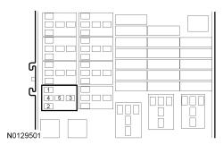
Yes REPAIR circuit GD149 (BK/GY) for an open. No GO to H6. - H6 CHECK THE THIRD ROW POWER SEAT RELAY FOR VOLTAGE AND GROUND
- Disconnect: Third Row Power Seat Relay.
- Verify the vehicle is in PARK and the liftgate is open.
- Verify the courtesy lights are on. If needed, close and open any door on the vehicle.
- Measure:
Positive Lead Measurement / Action Negative Lead
Third Row Power Seat Relay, Socket Pin 2
Third Row Power Seat Relay, Socket Pin 1
Is the voltage greater than 11 volts?
Yes GO to H8. No GO to H7. - H7 CHECK THE THIRD ROW POWER SEAT RELAY FOR VOLTAGE
- Verify the vehicle is in PARK and the liftgate is open.
- Verify the courtesy lights are on. If needed, close and open any door on the vehicle.
- Measure:
Positive Lead Measurement / Action Negative Lead Third Row Power Seat Relay, Socket Pin 2 Ground
Is the voltage greater than 11 volts?
Yes REPAIR circuit GD120 (BK/GN) for an open. No REPAIR circuit CLN09 (YE/GN) for an open. - H8 CHECK THE THIRD ROW POWER SEAT RELAY FOR VOLTAGE
- Measure:
Positive Lead Measurement / Action Negative Lead Third Row Power Seat Relay, Socket Pin 3 Ground
Is the voltage greater than 11 volts?
Yes GO to H9. No VERIFY BJB fuse 22 (30A) is OK. If the fuse is OK, REPAIR the circuit. If not OK, REFER to the OEM ELECTRICAL WIRING DIAGRAM INTRODUCTION to identify possible causes of the circuit short. - Measure:
- H9 CHECK THE CIRCUIT BETWEEN THE PFSM AND THE THIRD ROW POWER SEAT RELAY FOR AN OPEN
- Ignition OFF.
- Measure:
Positive Lead Measurement / Action Negative Lead C4250A-8 Third Row Power Seat Relay, Socket Pin 5
Is the resistance less than 3 ohms?
Yes INSTALL a new third row power seat relay. No REPAIR the circuit. - H10 CHECK THE PFSM ENABLE CIRCUIT FOR A SHORT TO VOLTAGE
- Disconnect: PFSM C4250E
.
- To access the PFSM, Refer to Power-Fold Seat Module (PFSM) .
- Disconnect: BCM C2280C .
- Ignition ON.
- Measure:
Positive Lead Measurement / Action Negative Lead C4250E-4 Ground
Is any voltage present?
Yes REPAIR the circuit. CLEAR the DTCs. TEST the system for normal operation. No GO to H11. - Disconnect: PFSM C4250E
.
- H11 CHECK THE PFSM ENABLE CIRCUIT FOR AN OPEN
- Ignition OFF.
- Disconnect: PFSM C4250E
.
- To access the PFSM, Refer to Power-Fold Seat Module (PFSM) .
- Disconnect: BCM C2280C .
Is the resistance less than 3 ohms?
Yes GO to H21. No REPAIR the circuit. - H12 CHECK THE PFSM ENABLE CIRCUIT FOR A SHORT TO GROUND
- Ignition OFF.
- Disconnect: PFSM C4250E
.
- To access the PFSM, Refer to Power-Fold Seat Module (PFSM) .
- Disconnect: BCM C2280C .
- Measure:
Positive Lead Measurement / Action Negative Lead C4250E-4 Ground
Is the resistance greater than 10, 000 ohms?
Yes GO to H21. No REPAIR the circuit. - H13 CHECK THE PFSM ENABLE CIRCUIT FOR VOLTAGE
- Disconnect: PFSM C4250E
.
- To access the PFSM, Refer to Power-Fold Seat Module (PFSM) .
- Verify the vehicle is in PARK and the liftgate is open.
- Verify the courtesy lights are on. If needed, close and open any door on the vehicle.
- Measure:
Positive Lead Measurement / Action Negative Lead C4250E-4 Ground
Is the voltage greater than 11 volts?
Yes GO to H14. No GO to H21. - Disconnect: PFSM C4250E
.
- H14 CHECK FOR VOLTAGE TO THE SEAT CONTROL SWITCH
- Connect: PFSM C4250A (if previously disconnected).
- Remove the third row seat control switch, but do not disconnect the electrical connector at this time. Refer to Seat Control Switch .
- Verify the vehicle is in PARK and the liftgate is open.
- Verify the courtesy lights are on. If needed, close and open any door on the vehicle.
- With all of the switch buttons at rest and seat select set to BOTH, measure:
Positive Lead Measurement / Action Negative Lead
Third Row Seat Control Switch C3199-2
Between 7 and 12.9 voltsGround Third Row Seat Control Switch C3199-3
Between 3.5 and 4.0 voltsGround Third Row Seat Control Switch C3199-4
Between 3.5 and 4.0 voltsGround
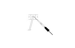
NOTE: This pinpoint test step directs testing circuits using a back-probe method. Use the special back-probe tool specified in the tool list in this article. Do not force test leads or other probes into connectors. Adequate care must be exercised to avoid connector terminal damage while making sure that good electrical contact is made with the circuit or terminal. Failure to follow these instructions may cause damage to wiring, terminals, or connectors and subsequent electrical faults.Do the voltages agree with the expected voltages in the table?
Yes GO to H19. No GO to H15. - H15 CHECK CIRCUITS FOR VOLTAGE WITH THE SEAT CONTROL SWITCH DISCONNECTED
- Disconnect: Third Row Seat Control Switch.
- Verify the vehicle is in PARK and the liftgate is open.
- Verify the courtesy lights are on. If needed, close and open any door on the vehicle.
- Measure:
Positive Lead Measurement / Action Negative Lead C3199-2
Greater than 10 voltsGround C3199-3
Greater than 4 voltsGround C3199-4
Greater than 4 voltsGround
Do the voltages agree with the expected voltages in the table?
Yes INSTALL a new third row seat control switch. Refer to Seat Control Switch . No GO to H16. - H16 CHECK THE SEAT CONTROL SWITCH CIRCUITS FOR A SHORT TO VOLTAGE
- Disconnect: PFSM C4250C .
- Disconnect: PFSM C4250D .
- Measure:
Positive Lead Measurement / Action Negative Lead C3199-2 Ground C3199-3 Ground C3199-4 Ground
Is any voltage present?
Yes REPAIR the affected circuit. No GO to H17. - H17 CHECK THE SEAT CONTROL SWITCH CIRCUITS FOR AN OPEN OR SHORT TO GROUND
- Measure:
Positive Lead Measurement / Action Negative Lead C3199-2 Ground C3199-3 Ground C3199-4 Ground Positive Lead Measurement / Action Negative Lead C3199-2 C4250C-1 C3199-5 C4250C-4 Positive Lead Measurement / Action Negative Lead C3199-3 C4250D-3 C3199-4 C4250D-2
Are the resistances less than 3 ohms between the seat control switch and the PFSM ; and greater than 10, 000 ohms between the seat control switch and ground?
Yes GO to H18. No REPAIR the affected circuit(s). - Measure:
- H18 CHECK THE SEAT CONTROL SWITCH CIRCUITS FOR A SHORT TOGETHER
- Measure:
Positive Lead Measurement / Action Negative Lead C3199-5 C3199-2 C3199-5 C3199-3 C3199-5 C3199-4 C3199-2 C3199-4 C3199-3 C3199-4 C3199-3 C3199-2
Are the resistances greater than 10, 000 ohms?
Yes GO to H22. No REPAIR the affected circuit. - Measure:
- H19 CHECK THE VOLTAGE AT THE SEAT CONTROL SWITCH CIRCUITS
- Disconnect: PFSM C4250E
.
- To access the PFSM, Refer to Power-Fold Seat Module (PFSM) .
NOTE: C4250E must be disconnected or inaccurate meter measurements may be taken.- Verify the vehicle is in PARK and the liftgate is open.
- Verify the courtesy lights are on. If needed, close and open any door on the vehicle.
- Measure:
Positive Lead Measurement / Action Negative Lead
With the switch in the (LH) position, Third Row Seat Control Switch C3199-2
Between 4.2 and 8.1 voltsGround With the switch in the (RH) position, Third Row Seat Control Switch C3199-2
Between 3.0 and 5.9 voltsGround With the switch in the (LH and RH) position, Third Row Seat Control Switch C3199-2
Between 7 and 12.9 voltsGround With the switch in the (FOLD) position, Third Row Seat Control Switch C3199-3
Between 1.2 and 1.5 voltsGround With the switch in the (NORMAL) position, Third Row Seat Control Switch C3199-4
Between 1.2 and 1.5 voltsGround With the switch in the (STOW) position, Third Row Seat Control Switch C3199-4
Between 1.8 and 2.2 voltsGround
NOTE: This pinpoint test step directs testing circuits using a back-probe method. Use the special back-probe tool specified in the tool list in this article. Do not force test leads or other probes into connectors. Adequate care must be exercised to avoid connector terminal damage while making sure that good electrical contact is made with the circuit or terminal. Failure to follow these instructions may cause damage to wiring, terminals, or connectors and subsequent electrical faults.Do the measured voltages agree with the table?
Yes GO to H22. No INSTALL a new third row seat control switch. Refer to Seat Control Switch . - Disconnect: PFSM C4250E
.
- H20 CHECK THE LATCH SWITCH AND LATCH MOTOR RETURN CIRCUITS FOR AN OPEN
- Disconnect: Left Seat Latch Switch.
- Gain access to the LH latch switch connector. Refer to Seat Control Switch .
- Disconnect: Left Seat Latch Motor.
- Disconnect: PFSM C4250A .
- Measure:
Positive Lead Measurement / Action Negative Lead C4250A-12 C4241-2 Positive Lead Measurement / Action Negative Lead C4250A-6 C4243-2
Are the resistances less than 3 ohms?
Yes GO to H18. No REPAIR the affected circuit. - Disconnect: Left Seat Latch Switch.
- H21 CHECK BCM CONNECTORS AND PINS FOR DAMAGE AND RETEST THE SYSTEM
- Disconnect and inspect all BCM connectors.
- Repair:
- corrosion (install new connector or terminals - clean module pins)
- damaged or bent pins - install new terminals/pins as necessary
- pushed-out pins - install new pins as necessary
- Reconnect all previously disconnected electrical connectors.
- Operate the seats and determine if the concern is still present.
Is the concern still present?
Yes CHECK OASIS for any applicable TSBs. If a TSB exists for this concern, DISCONTINUE this test and FOLLOW TSB instructions. If no TSBs address this concern, INSTALL a new BCM. REFER to Multifunction Electronic Modules - Without Intelligent Access or REFER to Multifunction Electronic Modules - With Intelligent Access . No The system is operating correctly at this time. The concern may have been caused by module connections. ADDRESS the root cause of any connector or pin issues. - H22 CHECK PFSM CONNECTORS AND PINS FOR DAMAGE AND RETEST THE SYSTEM
- Disconnect and inspect all PFSM connectors.
- Repair:
- corrosion (install new connector or terminals - clean module pins)
- damaged or bent pins - install new terminals/pins as necessary
- pushed-out pins - install new pins as necessary
- Reconnect all previously disconnected electrical connectors.
- Operate the seats and determine if the concern is still present.
Is the concern still present?
Yes CHECK OASIS for any applicable TSBs. If a TSB exists for this concern, DISCONTINUE this test and FOLLOW TSB instructions. If no TSBs address this concern, INSTALL a new PFSM. Refer to Power-Fold Seat Module (PFSM) . No The system is operating correctly at this time. The concern may have been caused by module connections. ADDRESS the root cause of any connector or pin issues.