Seat Backrest: Installation
- 3.
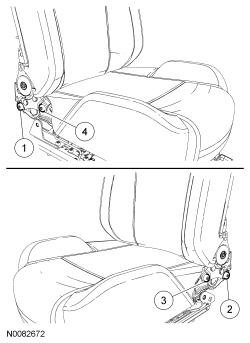
Install, but do not tighten, the 4 recliner-to-seat track bolts by hand.- If equipped, route the manual lumbar cable between the backrest and cushion and to the inside of the recliner.
- 4.
Tighten the 4 recliner-to-seat track bolts in the following sequence:- 1.
Tighten the rear outboard bolt to 48 Nm (35 lb-ft).
- 2.
Tighten the rear inboard bolt to 48 Nm (35 lb-ft).
- 3.
Tighten the front inboard bolt to 48 Nm (35 lb-ft).
- 4.
Tighten the front outboard bolt to 48 Nm (35 lb-ft).
- 1.
- 6.
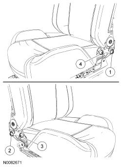
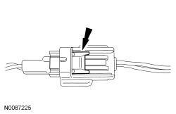
If equipped, connect the backrest electrical connector and attach the wire harness retainers under the seat.
- 9.
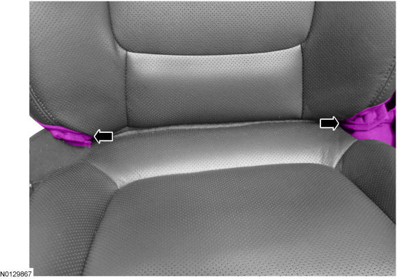
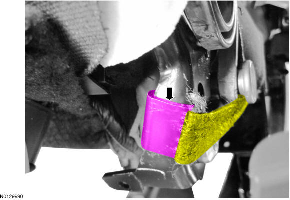
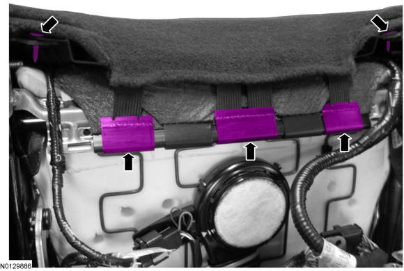
Attach the outboard cushion cover J-clip and strap onto the backrest frame.
NOTE:
Make sure the outboard cushion cover strap is routed below the backrest recliner spring mount.
- 10.
If equipped, install the manual lumbar cable in the following sequence:- Position the manual lumbar cable into the adjuster.
- Position the manual lumbar cable cover into the adjuster.
- Install the manual lumbar cable retainer.
- 12.
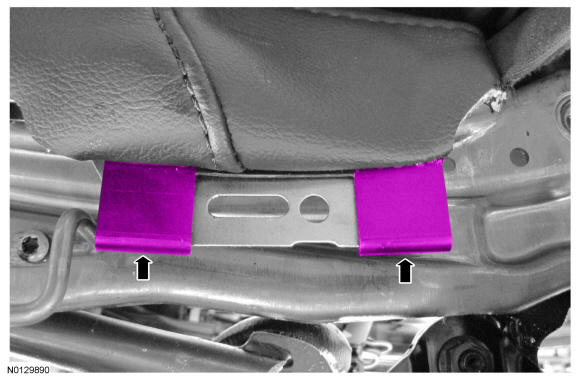
Install the cushion side shield in the following sequence:- Return all retaining clips back to the cushion side shield before installing the shield.
- Align and attach the retaining clips
- Install the screws at the front, center and rear of the cushion side shield.
- 14.
For power seats, install the power seat switch. Refer to Seat Control Switch .
- 19.
Install the carpet flap toe-kick retainers under the seat.- Attach the 3 J-clips onto the seat cushion frame.
- Install the 2 push pin retainers.
- 20.
Install the seat. Refer to Seat . If a passenger seat was serviced, do not carry out the prove out within the repower procedure, continue to the next step.
- 21.
- Make sure the voltage to the OCSM is greater than 8 volts and less than 18 volts.
- Make sure the OCS is not below 6 ° C (42.8 ° F) or above 36 ° C (96.7 ° F) when initiating the OCS reset process. If the vehicle has been exposed to extreme cold or hot temperatures, the vehicle must be exposed and kept at a temperature between 6 ° C (42.8 ° F) to 36 ° C (96.7 ° F) for a minimum of 30 minutes.
- Make sure nothing is present on the passenger seat before and during the OCS reset process.
- Prior to carrying out the OCS reset, make sure a minimum of 8 seconds has elapsed after cycling the ignition switch on.
If a passenger seat has been serviced, use a scan tool to carry out the OCS reset.
NOTE:
To prevent system failure, take the following precautions before carrying out the OCS system reset
WARNING:
Occupant Classification System (OCS) parts are calibrated as an assembly and must only be replaced in the configuration they are sold. Never separate parts of an assembly. Failure to follow this instruction may result in incorrect operation of the passenger airbag and increases the risk of serious personal injury or death in a crash.
WARNING:
Make sure the front passenger seat repair is complete, the seat and all attached components (head restraint, seat side shield, etc.) are correctly assembled, and the seat is correctly installed to the vehicle before using System Reset to rezero the seat weight. Failure to follow these instructions may result in incorrect operation of the occupant classification system (OCS) and increases the risk of serious personal injury or death in a crash.
- 22.
If the first system reset attempt was unsuccessful, carry out a thorough visual inspection of the following and repair any concerns found.- OCS connector and wiring for damage
- Pressure sensor hose for kinks and/or damage
- Seat-related wiring harness and body wiring harness terminals and connectors for damage
- 23.
Carry out a second OCS reset. If the second attempt is unsuccessful, install a new OCS service kit.
NOTE:
Cycle the ignition switch after the OCS reset.
- 24.
Prove out the Supplemental Restraint System (SRS) : Turn the ignition from ON to OFF. Wait 10 seconds, then turn the ignition back to ON and monitor the air bag warning indicator with the air bag modules installed. The air bag warning indicator illuminates continuously for approximately 6 seconds and then turns off. If a Supplemental Restraint System (SRS) fault is present, the air bag warning indicator will:- fail to light.
- remain lit continuously.
- flash.
- The flashing might not occur until approximately 30 seconds after the ignition has been turned from OFF to ON. This is the time required for the Restraints Control Module to complete the testing of the Supplemental Restraint System (SRS). If the air bag warning indicator is inoperative and a Supplemental Restraint System (SRS) fault exists, a chime sounds in a pattern of 5 sets of 5 beeps. If this occurs, diagnose and repair the air bag warning indicator and any Supplemental Restraint System (SRS) faults.