Instrument Panel: Removal
WARNING:
Before beginning any service procedure in this service information, refer to SAFETY WARNINGS
- 2.
Drain the coolant. REFER to Engine Cooling
- 3.
Recover the refrigerant. If equipped with DATC, REFER to Climate Control - DATC . If equipped with EMTC, REFER to Climate Control - EMTC .
- 4.
Remove the cowl panel grille. REFER to Front End Body Panels .
- 5.
Remove both front seats. REFER to Seating - 1st Row .
- 6.
Remove the front floor console. Refer to Console - Front, Floor .
- 7.
Disconnect the battery. REFER to Battery, Mounting and Cables .
- 8.NOTE: RH side shown in illustration, LH side similar.
Police vehicles only. Remove the LH side and RH side center lower instrument panel finish panels.
- 10.
Remove the steering wheel. REFER to Steering Column .
- 11.
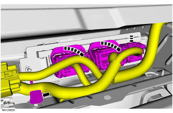
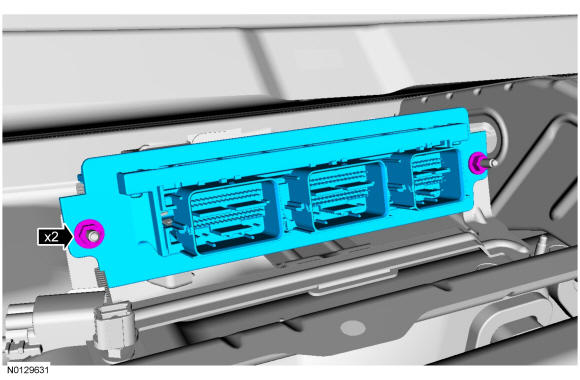
Disconnect the 3 PCM electrical connectors and position the harness aside.- 1.
Detach the PCM harness retainer.
- 1.
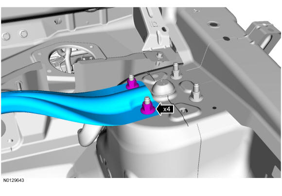
- 13.NOTE: LH side shown in illustration, RH side similar.
Remove the strut tower cross brace.
- 1.
To install, tighten to 55 Nm (41 lb-ft).
- 1.
- 15.
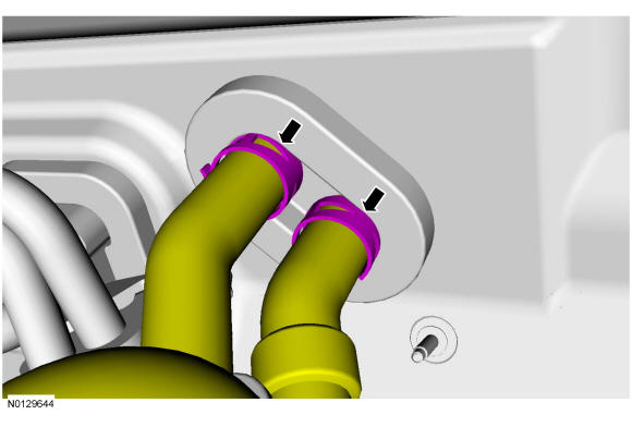
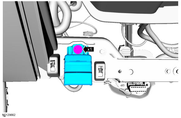
Remove the TXV manifold fastener and the manifold.- 1.
Discard the O-ring seals.
- 2.
To install, tighten to 8 Nm (71 lb-in).
- 1.
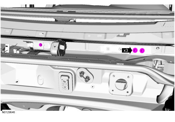
- 16.
Remove the LH and RH instrument panel-to-front of dash bolts.- 1.
To install, tighten to 25 Nm (18 lb-ft).
- 1.
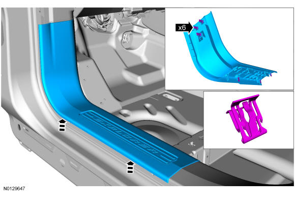
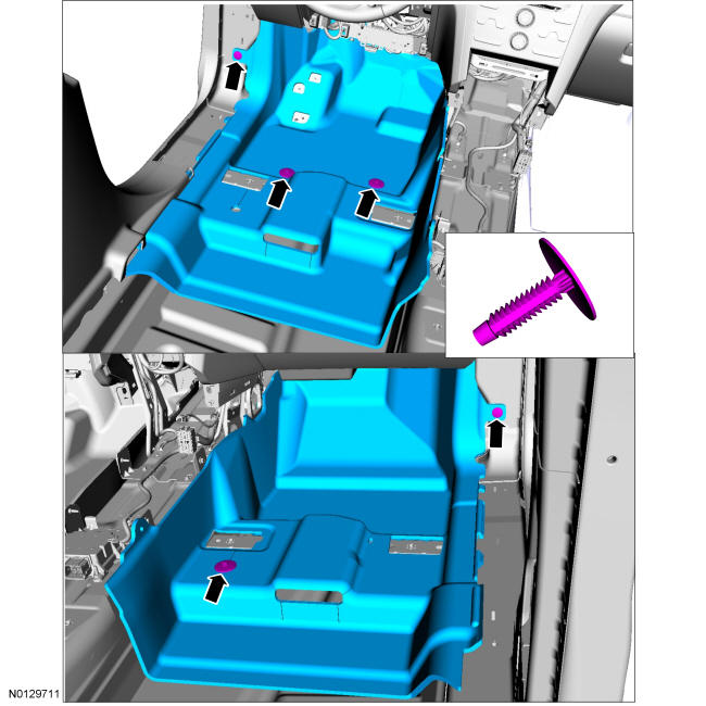
- 17.NOTE: LH side shown in illustration, RH side similar.
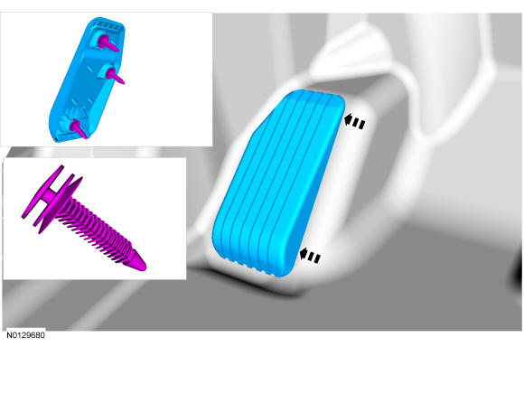
Remove the LH and RH front door scuff plate trim panels.
- 19.
Remove the LH and RH A-pillar trim panels. REFER to Interior Trim and Ornamentation .
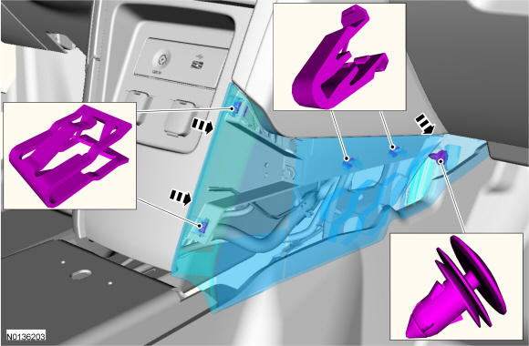
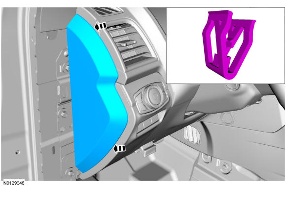
- 20.NOTE: LH side shown in illustration, RH side similar.
Remove the LH and RH instrument panel side trim panels.
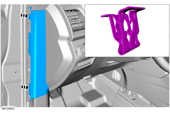
- 21.NOTE: LH side shown in illustration, RH side similar.
Remove the LH and RH cowl side trim covers.
- 22.
Remove the 2 bolts and remove the steering column cover trim panel.- 1.
To install, tighten to 1.9 Nm (17 lb-in).
- 2.
Pull outward to release the retainers.
- 1.
- 23.
Remove the 4 bolts and remove steering column cover assembly.- 1.
To install, tighten to 5 Nm (44 lb-in).
- 1.
- 24.
Remove the hood release handle bolt and remove the hood release handle.- 1.
To install, tighten to 5 Nm (44 lb-in).
- 1.
- 25.
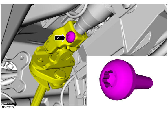
Remove the steering column pinch bolt and detach the steering column shaft from the steering column.- 1.
To install, tighten to 26 Nm (19 lb-ft).
- 2.
Discard the steering column shaft-to-steering column bolt.
- 1.
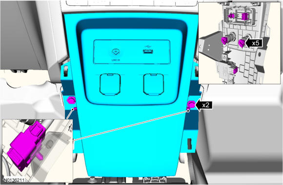
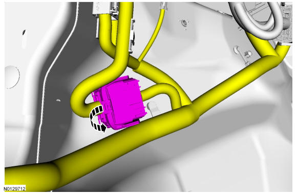
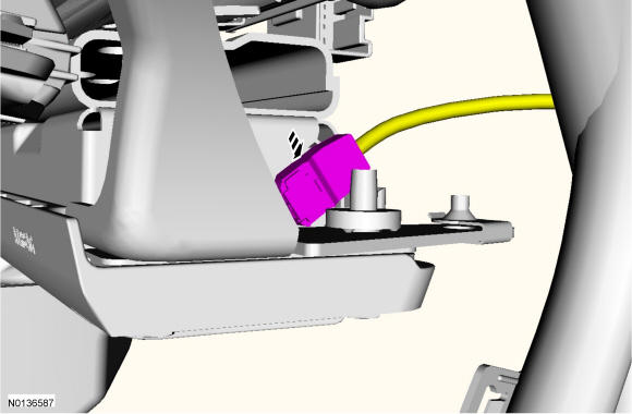
- 26.
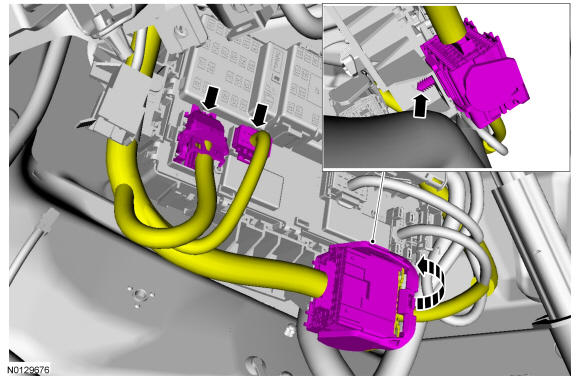
Disconnect the LH instrument panel bulkhead electrical connector and the 2 lower SJB electrical connectors.- 1.
Detach the instrument panel bulkhead electrical connector push pin from the SJB.
- 1.
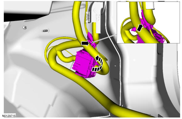
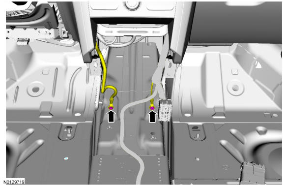
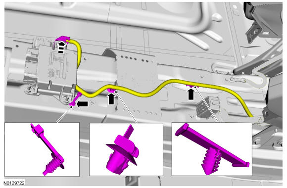
- 31.
Disconnect the RH bulkhead electrical connector and the antenna cable connector.- 1.
Release the antenna connector from the main harness.
- 1.
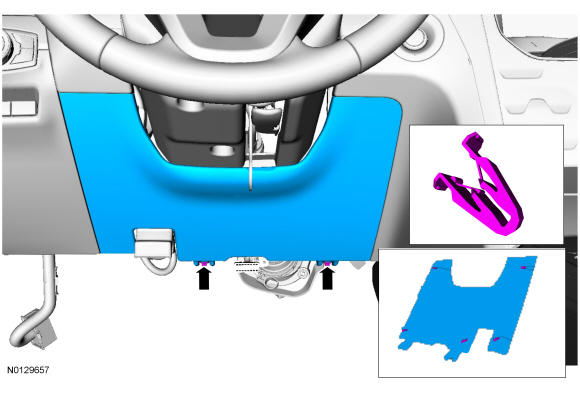
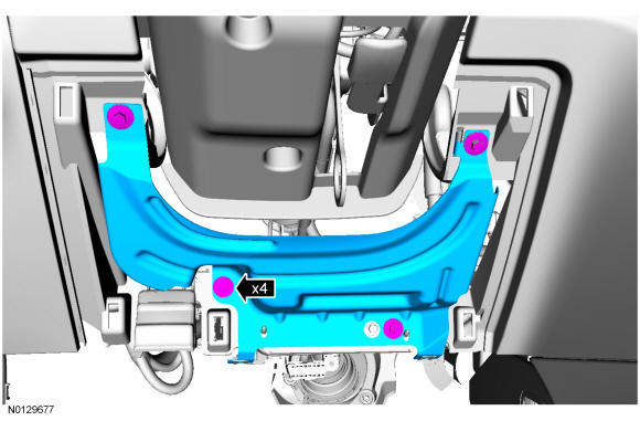
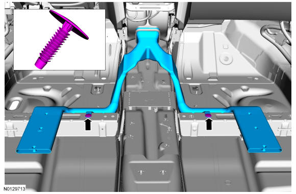
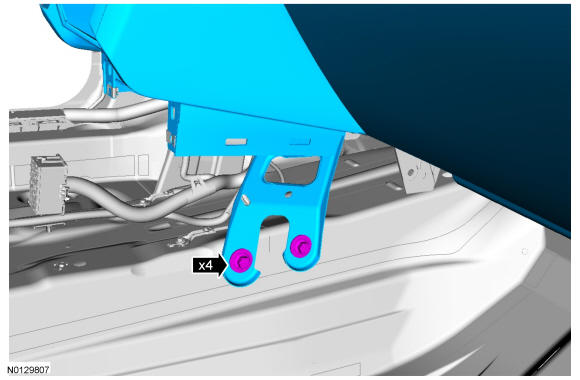
- 35.NOTE: RH side shown in illustration, LH side similar.
Remove the 4 instrument panel center support bracket bolts.
- 1.
To install, tighten to 25 Nm (18 lb-ft).
- 1.
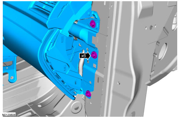
- 36.NOTE: To avoid damaging the instrument panel, an assistant is required when carrying out the following steps.NOTE: RH side shown in illustration, LH side similar.NOTE: Remove the bolts from one side completely and support the instrument panel before removing the bolts from the opposite side.
Remove the 3 LH and the 3 RH instrument panel side bolts.
- 1.
To install, tighten to 40 Nm (30 lb-ft).
- 1.
- 37.NOTE: Make sure not to damage the RH front door trim panel or the instrument panel when removing the instrument panel from the vehicle.NOTE: Make sure that all electrical connectors and wiring are not hindered before removing the instrument panel or damage to the components may occur.
Remove the instrument panel from the vehicle.
- 1.
Rotate the instrument panel face down and remove through the RH front door opening.
- 1.