PINPOINT TEST B : Incorrect Fuel Gauge Indication
- B1 CARRY OUT THE IPC SELF-TEST
- Using a scan tool, perform the IPC self-test.
Are any DTCs recorded?
Yes For DTC P0460:11 or DTC P1346:11, GO to B2. For DTC P0460:13 or DTC P1346:13, GO to B6. For DTC P1243:06, GO to B14. For all other DTCs, REFER to DTC Chart: IPC . No If equipped with an analog fuel gauge, GO to B13. If not equipped with an analog fuel gauge, GO to B14. - B2 CHECK THE FUEL INPUT FOR A SHORT TO GROUND
- Disconnect: Fuel Pump Assembly (DTC P0460:11).
- Disconnect: Fuel Level Sensor (DTC P1346:11).
- Ignition ON.
- Wait one minute.
- Using a scan tool, repeat the IPC on-demand self-test.
Is DTC P0460:13 or P1346:13 retrieved?
Yes GO to B16. No GO to B3. - B3 CHECK THE FUEL PUMP ASSEMBLY AND FUEL LEVEL SENSOR SIGNAL CIRCUIT FOR A SHORT TO GROUND
- Ignition OFF.
- Disconnect: IPC.
- Measure:
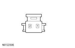
Positive Lead Measurement / Action Negative Lead C220-15 (DTC P0460:11) Ground C220-14 (DTC P1346:11) Ground
Is the resistance greater than 10, 000 ohms?
Yes For DTC P0460:11, GO to B4. For DTC P1346:11, GO to B5. No REPAIR the circuit in question. - B4 CHECK THE FUEL PUMP ASSEMBLY SIGNAL AND RETURN CIRCUITS FOR A SHORT TOGETHER
Is the resistance greater than 10, 000 ohms?
Yes GO to B21. No REPAIR the circuits. - B5 CHECK THE FUEL LEVEL SENSOR SIGNAL AND RETURN CIRCUITS FOR A SHORT TOGETHER
Is the resistance greater than 10, 000 ohms?
Yes GO to B21. No REPAIR the circuits. - B6 CHECK THE FUEL PUMP ASSEMBLY OR FUEL LEVEL SENSOR FOR AN OPEN
- Ignition OFF.
- Disconnect: Fuel Pump Assembly (DTC P0460:13).
- Disconnect: Fuel Level Sensor (DTC P1346:13).
- Ignition ON.
- Wait one minute.
- Using a scan tool, repeat the IPC self-test.
- Retrieve the IPC continuous DTCs.
Is DTC P0460:11 or P1346:11 retrieved?
Yes REMOVE the jumper wire. GO to B16. No REMOVE the jumper wire.For DTC P0460:13, GO to B7. For DTC P1346:13, GO to B10. - B7 CHECK THE FUEL LEVEL SIGNAL CIRCUIT FOR A SHORT TO VOLTAGE
- Ignition OFF.
- Disconnect: IPC.
- Ignition ON.
Is any voltage present?
Yes REPAIR the circuit in question. No GO to B8. - B8 CHECK THE FUEL LEVEL SIGNAL CIRCUIT FOR AN OPEN
- Ignition OFF.
Is the resistance less than 3 ohms?
Yes GO to B9. No REPAIR the circuit. - B9 CHECK THE FUEL LEVEL RETURN CIRCUIT FOR AN OPEN
Is the resistance less than 3 ohms?
Yes GO to B21. No REPAIR the circuit. - B10 CHECK THE FUEL LEVEL SENSOR SIGNAL CIRCUIT FOR A SHORT TO VOLTAGE
- Disconnect: IPC.
- Ignition ON.
Is any voltage present?
Yes REPAIR the circuit in question. No GO to B11. - B11 CHECK THE FUEL LEVEL SENSOR SIGNAL CIRCUIT FOR AN OPEN
Is the resistance less than 3 ohms?
Yes GO to B12. No REPAIR the circuit. - B12 CHECK THE FUEL LEVEL SENSOR RETURN CIRCUIT FOR AN OPEN
Is the resistance less than 3 ohms?
Yes GO to B21. No REPAIR the circuit. - B13 CARRY OUT THE IPC FUEL GAUGE ACTIVE COMMAND USING THE SCAN TOOL
- Ignition ON.
- Using a scan tool, view the IPC PIDs.
- Select and command the fuel gauge PID (Fuel Level) from 0% to 25%, 50%, 75% and 100% while observing the fuel gauge.
Does the fuel gauge begin at (E) empty, move to approximately 1/4, 1/2, 3/4 and F (full)?
Yes GO to B14. No GO to B21. - B14 INSPECT THE FUEL TANK
- Visually inspect the fuel tank for any damage or deformation.
Is the fuel tank OK?
Yes GO to B15. No INSTALL a new fuel tank. REFER to Tank and Lines . - B15 INSPECT THE FUEL TANK TRANSFER TUBE CONNECTIONS
- Remove the fuel pump assembly and the fuel level sensor. REFER to Fuel Tank and Lines and REFER to Fuel Tank and Lines .
- Inspect the fuel tank transfer tube, connections, the fuel pump assembly and the fuel level sensor for any damage or deformation.
Are the fuel tank transfer tube, connections, the fuel pump assembly and the fuel level sensor OK?
Yes For DTC P1243:06, INSTALL a new fuel pump module. REFER to Fuel Tank and Lines . For all other concerns, GO to B16. No INSTALL a new fuel tank transfer tube, fuel pump assembly or fuel level sensor as necessary. REFER to Fuel Tank and Lines and REFER to Fuel Tank and Lines . - B16 CHECK THE FUEL PUMP ASSEMBLY AND FUEL LEVEL SENSOR
- Inspect the fuel pump assembly and fuel level sensor connector.
- Repair:
- corrosion (install new connector or terminals - clean module pins)
- damaged pins - install new terminals/pins
- pushed-out pins - install new pins as necessary
- Reconnect the fuel pump assembly and fuel level sensor connector. Make sure they seat and latch correctly.
- Operate the system and determine if the concern is still present.
Is the concern still present?
Yes GO to B17. No The system is operating correctly at this time. The concern may have been caused by component connections. ADDRESS the root cause of any connector or pin issues. - B17 CHECK THE FUEL PUMP ASSEMBLY AND FUEL LEVEL SENSOR
- Remove the fuel pump assembly and fuel level sender. Refer to Fuel Tank and Lines .
- Measure the resistance
while slowly moving the float arm between the lower and upper stop position.
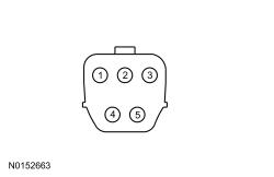
Positive Lead Measurement / Action Negative Lead C3127-1 (Component Side) C3127-2 (Component Side) Positive Lead Measurement / Action Negative Lead C3270-1 (Component Side) C3270-2 (Component Side)
Does the resistance slowly decrease from approximately 180 ohms at the lower stop to 10 ohms at the upper stop?
Yes For the fuel pump assembly, GO to B18. For the fuel level sensor, GO to B19. No GO to B20. - B18 CHECK THE FUEL PUMP ASSEMBLY SIGNAL AND RETURN CIRCUITS FOR A HIGH RESISTANCE
- Ignition OFF.
- Disconnect: IPC.
Is the resistance less than 3 ohms?
Yes REMOVE the fused jumper wire. GO to B21. No REPAIR the circuits for high resistance. - B19 CHECK THE FUEL LEVEL SENSOR SIGNAL AND RETURN CIRCUITS FOR A HIGH RESISTANCE
- Ignition OFF.
- Disconnect: IPC.
Is the resistance less than 3 ohms?
Yes REMOVE the fused jumper wire. GO to B21. No REPAIR the circuits for high resistance. - B20 CHECK THE FUEL LEVEL SENDER (FLOAT AND CARD)
- Disconnect the fuel level sender input wire from the fuel pump assembly or fuel level sensor.
- Measure the resistance between the fuel level sender (float and card) input wire and the fuel level sender (float and card) ground while slowly moving the float arm between the lower and upper stop position.
Does the resistance slowly decrease from approximately 180 ohms at the lower stop to 10 ohms at the upper stop?
Yes INSTALL a new fuel pump assembly or fuel level sensor. REFER to Fuel Tank and Lines . CLEAR the DTCs. No INSTALL a new fuel level sender (float and card). REFER to Fuel Tank and Lines . CLEAR the DTCs. - B21 CHECK FOR CORRECT IPC
- Disconnect and inspect the IPC connector.
- Repair:
- corrosion (install new connector or terminals - clean module pins)
- damaged pins - install new terminals/pins
- pushed-out pins - install new pins as necessary
- Reconnect the IPC connector. Make sure it seats and latches correctly.
- Operate the system and determine if the concern is still present.
Is the concern still present?
Yes CHECK On-Line Automotive Service Information System (OASIS) for any applicable Technical Service Bulletins (TSBs). If a Technical Service Bulletin (TSB) exists for this concern, DISCONTINUE this test and FOLLOW Technical Service Bulletin (TSB) instructions. If no Technical Service Bulletins (TSBs) address this concern, Refer to IPC Hardware Testing . No The system is operating correctly at this time. The concern may have been caused by module connections. ADDRESS the root cause of any connector or pin issues.