Customer Satisfaction Program 21B11 - Supplement #2 - 2ND Row Inflatable Seat Belt (21B11)
Reference number: 21B11
CUSTOMER SATISFACTION PROGRAM 21B11 - SUPPLEMENT #2 - 2ND ROW INFLATABLE SEAT BELT
SERVICE CAMPAIGN BULLETIN
| FORD: | 2014-2016 Explorer |
CUSTOMER SATISFACTION PROGRAM 21B11 - SUPPLEMENT #2
SUBJECT
Customer Satisfaction Program 21B11 - Supplement #2
Certain 2014-2016 Model Year Explorer Vehicles 2nd Row Inflatable Seat Belt
REF
Customer Satisfaction Program 21B11 - Supplement #1
Certain 2014-2016 Model Year Explorer Vehicles 2nd Row Inflatable Seat Belt
REASON FOR THIS SUPPLEMENT
- Service Action: Updated to reinforce the need to check for DTC's.
- ATTACHMENTS: Changes made to the technical instructions regarding replacement of the wiring harness.
- LABOR ALLOWANCES: Labor allowance descriptions have been updated for clarity. Only one labor operation code can be claimed per vehicle.
PROGRAM TERMS
This program will be in effect from January 21, 2022 to January 21, 2023. There is no mileage limit for this program.
AFFECTED VEHICLES
| Vehicle | Model Year | Assembly Plant | Build Dates |
|---|---|---|---|
| Explorer | 2014 | Chicago Plant Build | February 18, 2013 through June 2, 2014 |
| Explorer | 2015 | Chicago Plant Build | February 17, 2014 through May 4, 2015 |
| Explorer | 2016 | Chicago Plant Build | September 19, 2014 through February 28, 2016 |
Affected vehicles are identified in OASIS and FSA VIN Lists.
REASON FOR THIS PROGRAM
In all of the affected vehicles, the air bag light may illuminate as a result of a worn or damaged connection to the rear inflatable seat belt connector.
SERVICE ACTION
Dealers are to inspect for DTC codes and reposition or replace the wiring harness pigtail as necessary. This service must be performed on all affected vehicles at no charge to the vehicle owner.
OWNER NOTIFICATION MAILING SCHEDULE
Owner letters were mailed the week of February 7, 2022. Dealers should repair any affected vehicles that arrive at their dealerships, whether or not the customer has received a letter.
ATTACHMENTS
- Attachment I: Administrative Information
- Attachment II: Labor Allowances and Parts Ordering Information
- Attachment III: Technical Information
- Owner Notification Letters
QUESTIONS & ASSISTANCE
For questions and assistance, contact the Special Service Support Center (SSSC) via the SSSC Web Contact Site. The SSSC Web Contact Site can be accessed through the Professional Technician Society (PTS) website using the SSSC link listed at the bottom of the OASIS VIN report screen or listed under the SSSC tab.
Sincerely,

David J. Johnson
ATTACHMENT I
Customer Satisfaction Program 21B11 - Supplement #2
Certain 2014-2016 Model Year Explorer Vehicles 2nd Row Inflatable Seat Belt
OASIS ACTIVATION
OASIS was activated on January 21, 2022.
FSA VIN LISTS ACTIVATION
FSA VIN Lists has been available through https://web.fsavinlists.dealerconnection.com since January 21, 2022. Owner names and addresses have been available since February 21, 2022.
SOLD VEHICLES
- Owners of affected vehicles will be directed to dealers for repairs.
- Immediately contact any of your affected customers whose vehicles are not on your VIN list but are identified in OASIS. Give the customer a copy of the Owner Notification Letter (when available) and schedule a service date.
- Correct other affected vehicles identified in OASIS which are brought to your dealership.
- Dealers are to prioritize repairs of customer vehicles over repairs of new and used vehicle inventory.
STOCK VEHICLES
- Correct all affected units in your new vehicle inventory before delivery.
- Use OASIS to identify any affected vehicles in your used vehicle inventory.
TITLE BRANDED/SALVAGED VEHICLES
Affected title branded and salvaged vehicles are eligible for this service action.
OWNER REFUNDS
- Ford Motor Company is offering a refund for owner-paid repairs covered by this program if the repair was performed before the date of the Owner Notification Letter. This refund offer expires January 21, 2023.
- Dealers are also pre-approved to refund owner-paid emergency repairs that were performed away from an authorized servicing dealer after the date of the Owner Notification Letter. Noncovered repairs, or those judged by Ford to be excessive, will not be reimbursed.
- Refunds will only be provided for the cost associated with replacing the 2nd row inflatable seat belt.
RENTAL VEHICLES
Rental vehicles are not approved for this program.
ADDITIONAL REPAIR (LABOR TIME AND/OR PARTS)
Additional repairs identified as necessary to complete the FSA should be managed as follows:
- For related damage and access time requirements, refer to the Warranty and Policy Manual/Section 6 - Ford & Lincoln Program Policies/General Information & Special Circumstances for FSA's/Related Damage.
- For vehicles within new vehicle bumper-to-bumper warranty coverage, no SSSC approval is required, although related damage must be on a separate repair line with the "Related Damage" radio button checked.
- Ford vehicles - 3 years or 36,000 miles
- For vehicles outside new vehicle bumper-to-bumper warranty coverage, submit an Approval Request to the SSSC Web Contact Site prior to completing the repair.
CLAIMS PREPARATION AND SUBMISSION
- Claim Entry
: Enter claims using Dealer Management System (DMS) or One Warranty Solution (OWS) online.
- When entering claims:
- Claim type 31: Field Service Action. The FSA number 21B11 is the sub code.
- Customer Concern Code (CCC): A79
- Condition Code (CC): X4
- Causal Part Number: 14B686
- Part Quantity: 0
- For additional claims preparation and submission information, refer to the Recall and Customer Satisfaction Program (CSP) Repairs in the OWS User Guide.
- When entering claims:
- Related Damage/Additional labor and/or parts
: Must be claimed as Related Damage on a separate repair line from the FSA with same claim type and sub code as described in Claim Entry above.IMPORTANT: Click the Related Damage Indicator radio button.
- Refunds
: Submit refunds on a separate repair line.
- Program Code: 21B11
- Misc. Expense: REFUND
- Misc. Expense: ADMIN
- Misc. Expense: 0.2 Hrs.
- Additional parts not listed in the parts section : Additional parts such as Black PVC Tape, and Tie Straps, may be submitted on the same repair line on which the FSA is claimed. Additional parts totaling more than $3.50 requires prior approval from the SSSC.
- Provision for locally obtained Black PVC Tape and Tie Straps
: Submit refunds on a separate repair line.
- Program Code: 21B11
- Misc. Expense: Claim up to $3.50
- Misc. Expense: OTHER
ATTACHMENT II
Customer Satisfaction Program 21B11 - Supplement #2
Certain 2014-2016 Model Year Explorer Vehicles 2nd Row Inflatable Seat Belt
LABOR ALLOWANCES
| Description | Labor Operation | Labor Time |
|---|---|---|
| Check DTC's, (NO DTC CODES PRESENT), remove both seats and reposition harness on seats | 21B11B | 1.6 Hours |
| Check DTC's (ONE DTC CODE PRESENT), remove the NON-DTC code seat and reposition harnesses on seat, and replace wiring harness pig tail on the seat with corresponding DTC code | 21B11C | 2.2 Hours |
| Check DTC's (BOTH DTC CODES PRESENT), replace wiring harness pig tails on both seats | 21B11D | 2.9 Hours |
PARTS REQUIREMENTS/ORDERING INFORMATION
SSSC Web Contact Site:
To place an order for K-coded parts submit a VIN-specific Part Order contact via the SSSC Web Contact Site.
| Part Number | Description | Order Quantity | Claim Quantity | ||
|---|---|---|---|---|---|
| JU5Z-14A594-A | Snap On Retainer - Can only be claimed with Labor Operations B and C 2 for B 1 for C 0 for D |
Up to 2 As Required | Up to 2 As Required | ||
| EB5Z-14A099-C | Meshed Sleeve - Can only be claimed with Labor Operations B and C 2 for B 1 for C 0 for D |
Up to 2 As Required | Up to 2 As Required | ||
| (1)HU5Z-14A163-C | Tie Strap - Can only be claimed with Labor Operations B and C 2 for B 1 for C 0 for D |
Up to 2 As Required | Up to 2 As Required | ||
| FU2Z-14S411-RB | Pigtail - Can only be claimed with Labor Operations C and D 0 for B 1 for C 2 for D |
Up to 2 As Required | Up to 2 As Required | ||
|
NOTE:
Dealers will be notified via a DOES II communication if circumstances warrant a change in part supply strategy and when open ordering resumes. |
|||||
DEALER PRICE
For latest prices, refer to DOES II.
PARTS RETENTION, RETURN, & SCRAPPING
Follow the provisions of the Warranty and Policy Manual, Section 1 - WARRANTY PARTS RETENTION AND RETURN POLICIES. If a replaced part receives a scrap disposition, the part must be scrapped in accordance with all applicable local, state and federal environmental protection and hazardous material regulations. Federal law prohibits selling motor vehicle parts or components that are under safety, compliance, or emissions recall.
EXCESS STOCK RETURN
Excess stock returned for credit must have been purchased from Ford Customer Service Division in accordance with Policy Procedure Bulletin 4000.
REPLACED FSA PARTS INSPECTION AND SIGN OFF
Effective March 1st 2021 all parts replaced as part of an FSA repair with a repair order open date of March 1st 2021 or later must be inspected and signed off on the repair order by a member of your dealers fixed operations management team or an employee the task has been delegated to. If the task is to be delegated to a non-management employee, the employee needs to be someone other than the technician who completed the repair and needs to understand the importance of completing this task consistently and accurately.
- All parts replaced as part of an FSA repair should be returned to the parts department following the Warranty Parts Retention and Return Policies.
- Inspect the replaced parts to verify the FSA repair was completed.
- If the FSA repair is found to be complete, the designated employee signs the repair order line or parts return stamp area (electronic or hand signed) for the FSA repair indicating the parts were inspected and validated to have been replaced.
- After the parts have been inspected, they should be handled based on the guidance in the parts status report in the Online Warranty System (Hold, Return, CORE, Scrap, etc.).
- This process is subject to review during warranty audits for FSA repairs with a repair order open date of March 1st 2021 or later. Any eligible FSA claims requiring parts replacement, found not to have been inspected and signed off during a warranty audit will be subject to chargeback and consideration for enrollment into the Dealer Incomplete Recall Repair Process.
ATTACHMENT III
CUSTOMER SATISFACTION PROGRAM 21B11 -S2
CERTAIN 2014-2016 MODEL YEAR EXPLORER VEHICLES - SECOND ROW INFLATABLE SEATBELT
SERVICE PROCEDURE
- Connect Integrated Diagnostic System (IDS) and check for Diagnostic Trouble Code's (DTC's) B141B and/or B141C. NOTE: DTC's may indicate possible internal wire damage in the seat wire harness.NOTE: B141B is the left wiring harness and B141C is the right wiring harness.
- Are one or both of the following DTC codes present: B141B and/or B141C?
YES - Proceed to Wire Harness Repair and Re-Routing (B141B and/or B141C Present) Procedure on Page 8.
NO - Proceed to Wire Harness Stress Relief Procedure below.
WIRE HARNESS STRESS RELIEF PROCEDURE
- Remove the affected second row seat. Please follow the Workshop Manual (WSM) procedures in Section 501-01B.
- Place the affected seat on a work bench with underside of the seat facing up.
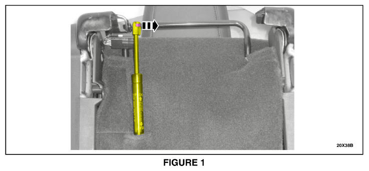
- If equipped, disengage the clip securing the hydraulic ram and position the hydraulic ram aside. See Figure 1.
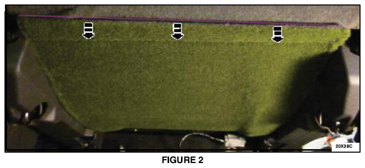
- Release the seat cushion cover J-clip and position aside the seat cover. See Figure 2.
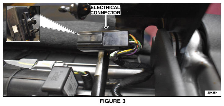
- Disconnect the electrical connector push pins from the seat frame. See Figure 3.
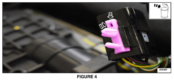
- Remove and discard the electrical connector push pin retainer. See Figure 4.
- Install the new electrical connector push pin retainer by reversing the removal steps. See Figure 4.
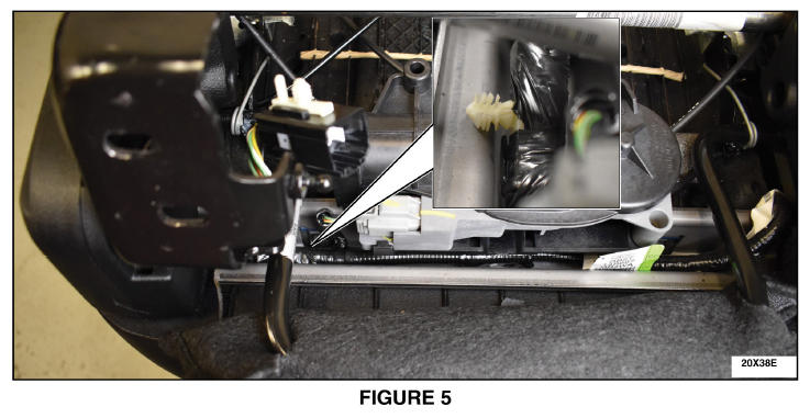
- Disconnect the wire harness push pin retainer closest to the electrical connector from the seat frame. See Figure 5.
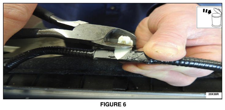
- Using a suitable tool remove the head from the wire harness push pin retainer that was disconnected in the previous step. See Figure 6.
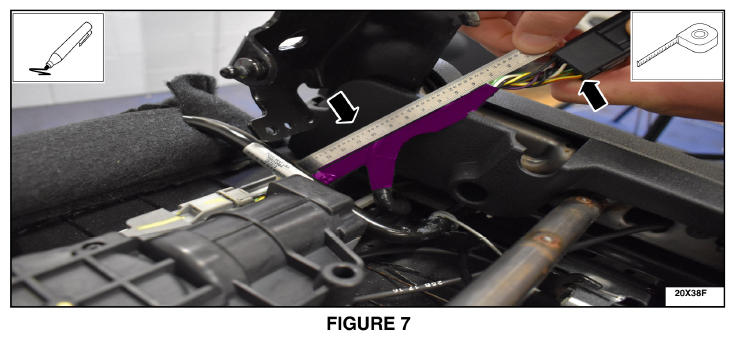
- Measure the distance from the back of the connector to the branch. Add 25mm (1 in) from that point and mark on the main harness and the take out (branch off wire). See Figure 7.
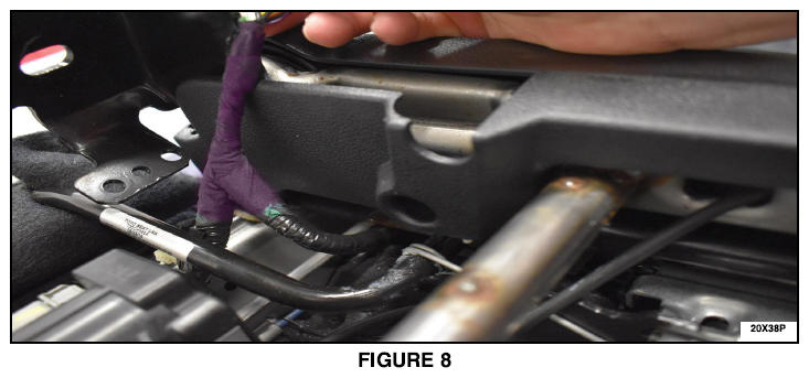
- Remove all tape and convolute tubing from wiring back of the connector to the marks made in the prior step. See Figure 8.
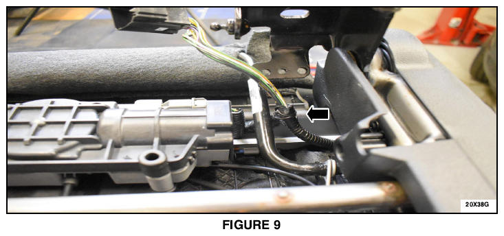
- Relocate the take out (branch off wire) and spot tape it to the main harness at the end of the convolute tubing. See Figure 9
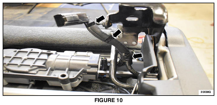
- Install a mesh sleeve and apply electrical tape to the ends and middle of the sleeve. See Figure 10.
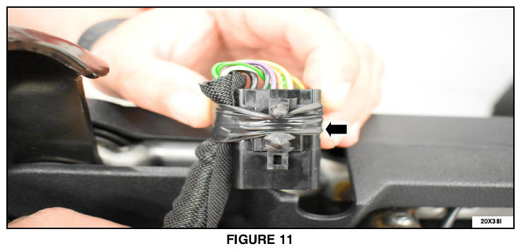
- Wrap the wire around the connector and secure with 3 wraps of electrical tape going between the new electrical connector push pin retainer. See Figure 11.
- Reconnect the electrical connector to the seat frame. See Figure 3.
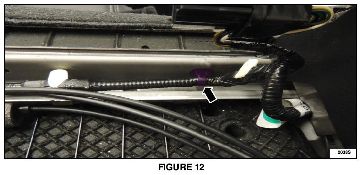
- Install a new
zip-tie wire harness electrical connector retainer (one closest to the electrical connector) to secure the wire harness to the seat frame. See Figure 12.
- Slide the seat forward, backward and tilt it to insure no wires are taught.
- Position the seat cushion cover and engage the J-clip. See Figure 2.
- If equipped, reattach the clip securing the hydraulic ram. See Figure 1.
- Reinstall the affected second row seat. Please follow the WSM procedures in Section 501-01B. This completes the recall.
WIRE HARNESS REPAIR AND RE-ROUTING (B141B and/or B141C Present)
- Disconnect battery cable to ground. Please follow the Workshop Manual (WSM) procedures in Section 414-01.
- Remove the seat bottom cover from the affected seat. Please follow the WSM procedures in Section 501-10.
- On the affected seat, disconnect the electrical connector and remove the connector and wiring harness pushpin from its mounting on the seat frame.
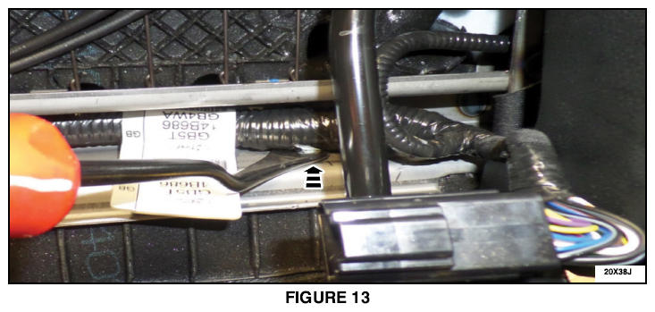
- On the affected seat, follow the seat harness and locate the next harness retaining pushpin closest to the electrical connector and remove it. See Figure 13.
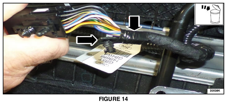
- On the male side connector of the affected seat where the wiring harness is taped to the harness - pushpin retainers, remove the retaining tape and the harness pushpin. Discard the pushpin. See Figure 14.
- Determine the vehicle's second row seat configuration.
- If the vehicle is equipped with the 60/40 seats proceed to Step 7.
- If the vehicle is equipped with second row armrest chairs proceed to Step 15.
- For vehicles with 60/40 seats, perform the following procedure:
- On the driver side cut the wires on the female side of C3133 and replace them with the new wiring harness. Only replace the length of wire removed from the harness. Solder the new wire to the existing circuits. Refer to Section 5 of the Wiring Diagram for the solder-splicing method.
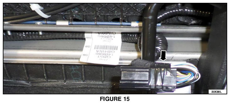
- On the male connector create a 15-20 mm (1/2-3/4") loop with the wiring harness and secure the harness to the connector using electrical tape. Make sure the wire loop does not contact the seat trim. Wrap the harness and connectors 3 times to provide harness stress relief and to prevent damage to the connector terminals when the seat is folded forward. See Figure 15.
- Reconnect the electrical connector.
- Reattach the electrical connector to the seat mounting with the existing pushpin.
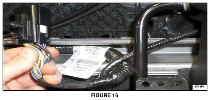
- On the passenger side, take the connector and route the seat harness to the other side of the black bar. See Figure 16.
- Reconnect the electrical connector.
- Attach the electrical connector to the seat mounting with the existing pushpin. Proceed to Step 21.NOTE: For vehicles with second row armrest chairs perform the following procedure:
- On both the passenger and driver side seat take the connectors and route the seat harness to the other side of the black vertical bar. See Figure 16.
- Cut the wires for both female connectors C3133 and C3134, and replace them with the new wiring harness. Only replace the length of wire removed from the harness. Solder the new wire to the existing circuits. Refer to Section of the Wiring Diagram for the solder-splicing method.
- On the male connector side, create a 15-20 mm (1/2-3/4") loop with the wiring harness and secure the harness to the connector using electrical tape. Make sure the wire loop does not contact the seat trim. Wrap the harness and connectors 3 times to provide harness stress relief and to prevent damage to the connector terminals when the seat is folded forward. See Figure 15.
- Reconnect the electrical connectors.
- Reattach both electrical connectors to the seat mounting with the existing pushpins.
- Reattach the seat bottom cover. Please follow the WSM procedures in Section 501-10.
- Reconnect the battery cable to ground. Please follow the WSM procedures in Section 414-01.
- Use IDS to recheck and clear DTC's. If DTC's are present please follow the WSM procedures in Section 501-20B.