TIRE PRESSURE MONITORING SYSTEMS (TPMS) IDENTIFICATION
TIRE PRESSURE MONITORING SYSTEMS (TPMS) IDENTIFICATION
TECHNICAL SERVICE BULLETIN
Reference Number(s): 25-7012, Date of Issue:
February 10, 2025
Superceded Bulletin(s): 23-7172, Date of Issue:
February 10, 2025
NOTE:
This bulletin supersedes 23-7172. Reason for update: revised Table 1 (Figure 40)
SUMMARY
This article supersedes GSB 23-7172 to update the vehicle model years affected and Service Information.
This bulletin contains information on TPMS
identification of Ford versus non-Ford sensors along with warrantable versus non-warrantable concerns and examples.
SERVICE INFORMATION
TIRES OVERVIEW
Tires are designed to operate within a specific range of air pressures. The recommended inflation pressure is printed on the decal on the driver's doorjamb (B-Pillar). The decal specifies the proper tire inflation.
Tire pressure should be checked monthly as recommended in the Owner's Manual because all tires lose pressure over time.
A tire's inflation pressure cannot be judged by appearance alone. By the time a low profile radial tire looks low, it may already be 10 to 15 PSI underinflated.
The accuracy of some new inexpensive tire pressure gauges can be off by several PSI. Checking tire inflation pressure requires an accurate tire pressure gauge.
TPMS TECHNOLOGY
When the vehicle begins to move, a switch inside the sensor activates the pressure measurement and signal sending function. At about 20 mph (32 km/h), the sensor begins measuring the pressure every 30 seconds and transmits the results once each minute to the control module.
The sensors transmit tire pressure data to the control module at 315 MHz or 433 MHz depending on the vehicle model year. Trailer TPMS
and most export vehicles use 433 MHz.
After inflating the tires to the recommended inflation pressure, the vehicle must be driven at 20 mph (32 km/h) or more for a few minutes for the light to turn off.
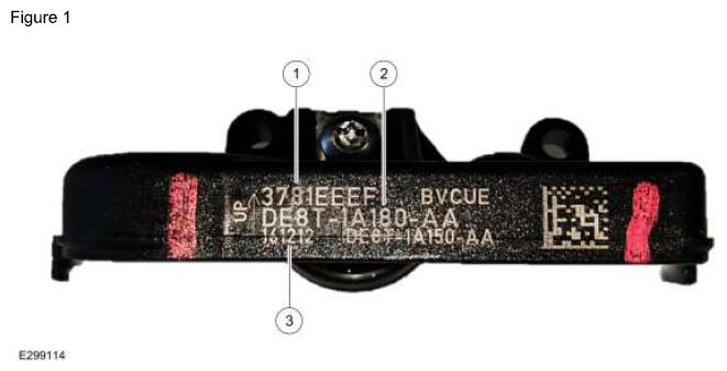
FORD ORIGINAL EQUIPMENT (OE) SENSOR (EDISON HOUSING) MARKINGS AND PART DETAILS (FIGURES 1-2)
ITEM DESCRIPTION
| Item |
Description |
| 1 |
Sensor ID |
| 2 |
Ford Part Number |
| 3 |
Sensor Build Date (Year/Month/Day) |
ITEM DESCRIPTION
| Item |
Description |
| 1 |
FoMoCo Label |
| 2 |
Pressure Port |
| 3 |
Do Not Discard Warning |
| 4 |
FCC Identification and Frequency |
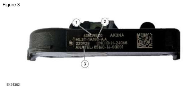
FORD OE SENSOR (POTTED FARADAY) MARKINGS AND PART DETAILS (FIGURES 3-4)
ITEM DESCRIPTION
| Item |
Description |
| 1 |
Sensor ID |
| 2 |
Ford Part Number |
| 3 |
Sensor Build Date (Year/Month/Day) |
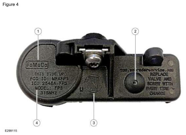
ITEM DESCRIPTION
| Item |
Description |
| 1 |
FoMoCo Label |
| 2 |
Pressure Port |
| 3 |
Do Not Discard Warning |
| 4 |
FCC Identification and Frequency |
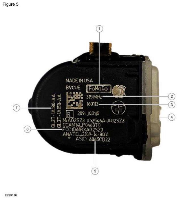
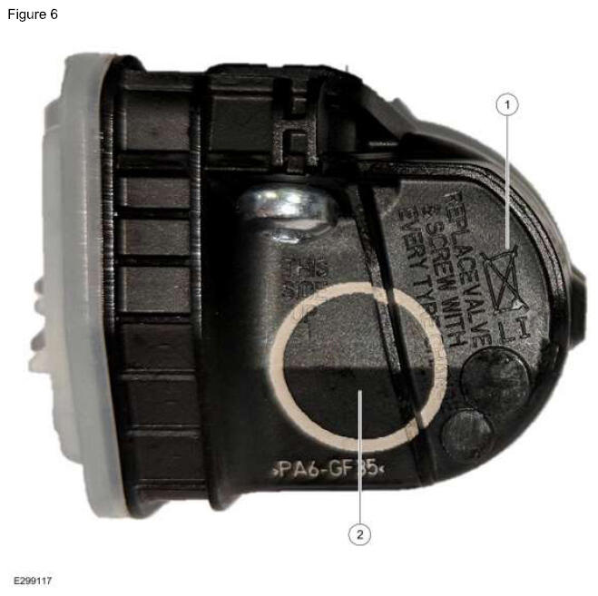
FORD OE SENSOR (FARADAY) MARKINGS AND PART DETAILS (FIGURES 5-6)
ITEM DESCRIPTION
| Item |
Description |
| 1 |
FoMoCO Label |
| 2 |
Sensor Frequency |
| 3 |
Sensor Build Date (Year/Month/Day) |
| 4 |
Pressure Port |
| 5 |
Sensor ID |
| 6 |
FCC Identification |
| 7 |
Ford Part Number |
ITEM DESCRIPTION
| Item |
Description |
| 1 |
Do Not Discard Warning |
| 2 |
Visual Identifier (Part Specific) |
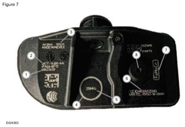
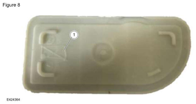
FORD OE SENSOR (MHSSI) MARKINGS AND PART DETAILS (FIGURES 7-8)
ITEM DESCRIPTION
| Item |
Description |
| 1 |
Sensor ID |
| 2 |
Ford Part Number |
| 3 |
Sensor Build Date (Year/Month/Day) |
| 4 |
Visual Identifier (Part Specific) |
| 5 |
Sensor Frequency |
| 6 |
FCC Identification |
| 7 |
FoMoCo Label |
| 8 |
Pressure Port |
ITEM DESCRIPTION
| Item |
Description |
| 1 |
Do Not Discard Warning |
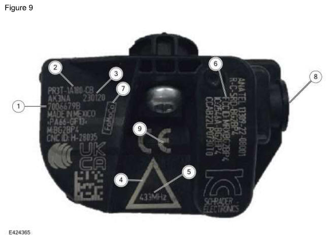
FORD OE SENSOR (BURNELL) MARKINGS AND PART DETAILS (FIGURE 9)
ITEM DESCRIPTION
| Item |
Description |
| 1 |
Sensor ID |
| 2 |
Ford Part Number |
| 3 |
Sensor Build Date (Year/Month/Day) |
| 4 |
Visual Identifier (Part Specific) |
| 5 |
Sensor Frequency |
| 6 |
FCC Identification |
| 7 |
FoMoCo Label |
| 8 |
Pressure Port |
| 9 |
Do Not Discard Warning |
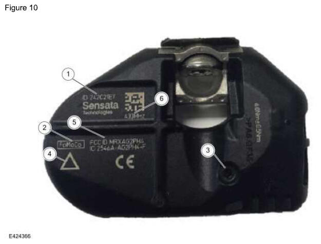
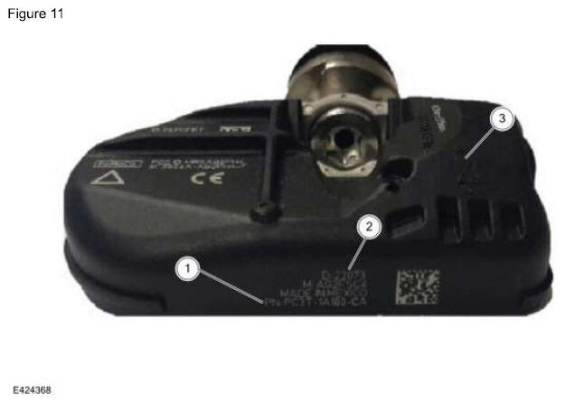
FORD OE SENSOR (STEEL CARCASS) MARKINGS AND PART DETAILS (FIGURES 10-11)
ITEM DESCRIPTION
| Item |
Description |
| 1 |
Sensor ID |
| 2 |
FoMoCo Label |
| 3 |
Pressure Port |
| 4 |
Visual Identifier (Part Specific) |
| 5 |
FCC Identification |
| 6 |
Sensor Frequency |
ITEM DESCRIPTION
| Item |
Description |
| 1 |
Ford Part Number |
| 2 |
Sensor Build Date (Year/Month/Day) |
| 3 |
Do Not Discard Warning |
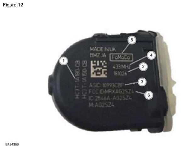
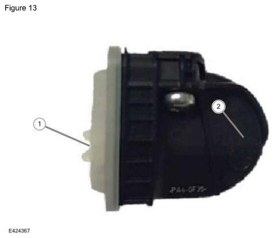
FORD OE SENSOR (TRAILER) MARKINGS AND PART DETAILS (FIGURES 12-13)
ITEM DESCRIPTION
| Item |
Description |
| 1 |
Ford Part Number |
| 2 |
Sensor Build Date (Year/Month/Day) |
| 3 |
Sensor ID |
| 4 |
Sensor Frequency |
| 5 |
FoMoCo Label |
| 6 |
FCC Identification |
ITEM DESCRIPTION
| Item |
Description |
| 1 |
Pressure Port |
| 2 |
Do Not Discard Warning |
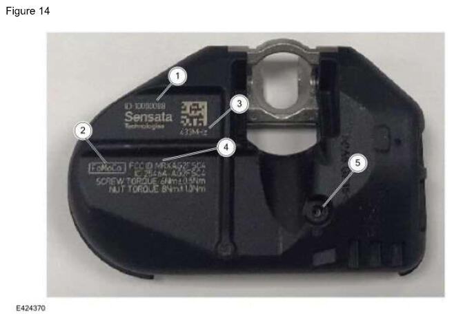
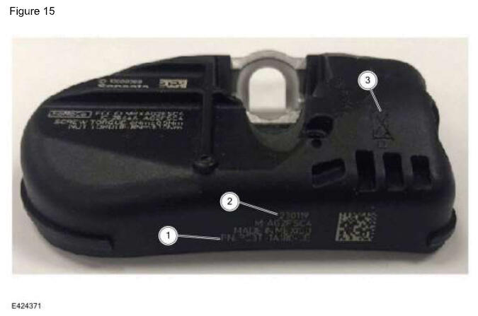
FORD OE SENSOR (TRAILER STEEL CARCASS) MARKINGS AND PART DETAILS (FIGURES 14-15)
ITEM DESCRIPTION
| Item |
Description |
| 1 |
Sensor ID |
| 2 |
FoMoCo Label |
| 3 |
Sensor Frequency |
| 4 |
FCC Identification |
| 5 |
Pressure Port |
ITEM DESCRIPTION
| Item |
Description |
| 1 |
Ford Part Number |
| 2 |
Sensor Build Date (Year/Month/Day) |
| 3 |
Do Not Discard Warning |
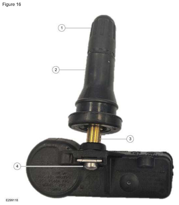
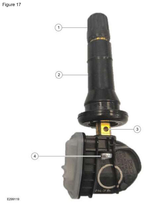
FORD OE SENSOR (EDISON/FARADAY) COMPONENTS (FIGURES 16-17)
NOTE:
When replacing the valve, make sure to replace the valve only, not the entire sensor kit. Otherwise, this is an over-repair and not warrantable.
ITEM DESCRIPTION
| Item |
Description |
| 1 |
Cap |
| 2 |
Valve Stem |
| 3 |
Valve Air Port |
| 4 |
Bolt |
ITEM DESCRIPTION
| Item |
Description |
| 1 |
Cap |
| 2 |
Valve Stem |
| 3 |
Valve Air Port |
| 4 |
Bolt |
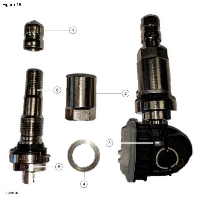
FORD OE SENSOR (BOLT-ON FARADAY) COMPONENTS (FIGURE 18)
NOTE:
When replacing the valve, make sure to replace the valve only, not the entire sensor kit. Otherwise, this is an over-repair and not warrantable.
ITEM DESCRIPTION
| Item |
Description |
| 1 |
Cap |
| 2 |
Hex Nut |
| 3 |
Bolt |
| 4 |
Washer |
| 5 |
Valve Air Port |
| 6 |
Valve Stem |
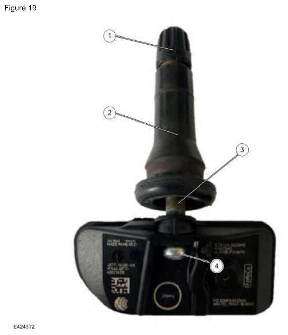
FORD OE SENSOR (MHSSI) COMPONENTS (FIGURE 19)
NOTE:
When replacing the valve, make sure to replace the valve only, not the entire sensor kit. Otherwise, this is an over-repair and not warrantable.
ITEM DESCRIPTION
| Item |
Description |
| 1 |
Cap |
| 2 |
Valve Stem |
| 3 |
Valve Air Port |
| 4 |
Bolt |
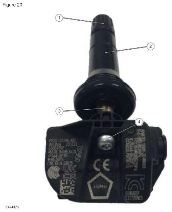
FORD OE SENSOR (BURNELL) COMPONENTS (FIGURE 20)
NOTE:
When replacing the valve, make sure to replace the valve only, not the entire sensor kit. Otherwise, this is an over-repair and not warrantable.
ITEM DESCRIPTION
| Item |
Description |
| 1 |
Cap |
| 2 |
Valve Stem |
| 3 |
Valve Air Port |
| 4 |
Bolt |
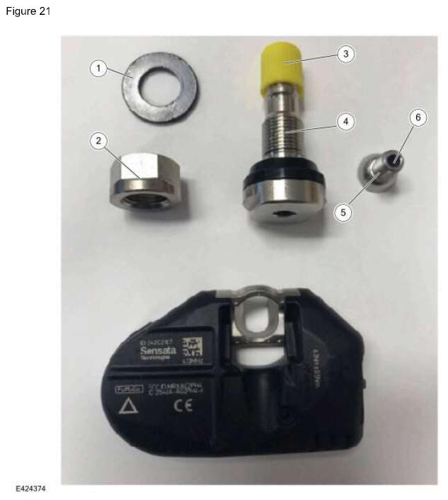
FORD OE SENSOR (STEEL CARCASS - STRAIGHT) COMPONENTS (FIGURE 21)
NOTE:
When replacing the valve, make sure to replace the valve only, not the entire sensor kit. Otherwise, this is an over-repair and not warrantable.
ITEM DESCRIPTION
| Item |
Description |
| 1 |
Washer |
| 2 |
Hex Nut |
| 3 |
Cap |
| 4 |
Valve Stem |
| 5 |
Bolt |
| 6 |
Valve Air Port (flows through bolt) |
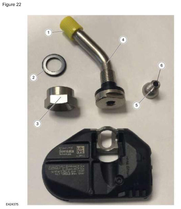
FORD OE SENSOR (STEEL CARCASS - BENT) COMPONENTS (FIGURE 22)
NOTE:
When replacing the valve, make sure to replace the valve only, not the entire sensor kit. Otherwise, this is an over-repair and not warrantable.
ITEM DESCRIPTION
| Item |
Description |
| 1 |
Cap |
| 2 |
Washer |
| 3 |
Hex Nut |
| 4 |
Valve Stem |
| 5 |
Bolt |
| 6 |
Valve Air Port (flows through bolt) |
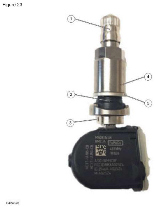
FORD OE SENSOR (TRAILER) COMPONENTS (FIGURE 23)
NOTE:
When replacing the valve, make sure to replace the valve only, not the entire sensor kit. Otherwise, this is an over-repair and not warrantable.
ITEM DESCRIPTION
| Item |
Description |
| 1 |
Cap |
| 2 |
Valve Stem |
| 3 |
Valve Air Port |
| 4 |
Hex Nut |
| 5 |
Washer |
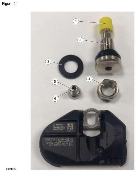
FORD OE SENSOR (TRAILER STEEL CARCASS) COMPONENTS (FIGURE 24)
NOTE:
When replacing the valve, make sure to replace the valve only, not the entire sensor kit. Otherwise, this is an over-repair and not warrantable.
ITEM DESCRIPTION
| Item |
Description |
| 1 |
Cap |
| 2 |
Valve Stem |
| 3 |
Washer |
| 4 |
Hex Nut |
| 5 |
Bolt |
| 6 |
Valve Air Port (flows through bolt) |
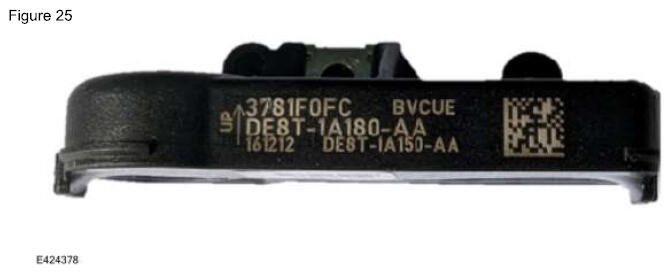
IDENTIFYING CORRECT FORD OE SENSOR (DE8TI EDISON) FOR A PARTICULAR VEHICLE (FIGURE 25)
1 - DE8T-1A180-**
PARTS INFORMATION
| Engineering Part Number |
Description |
| DE8T-1A180-** |
315 MHz Edison |
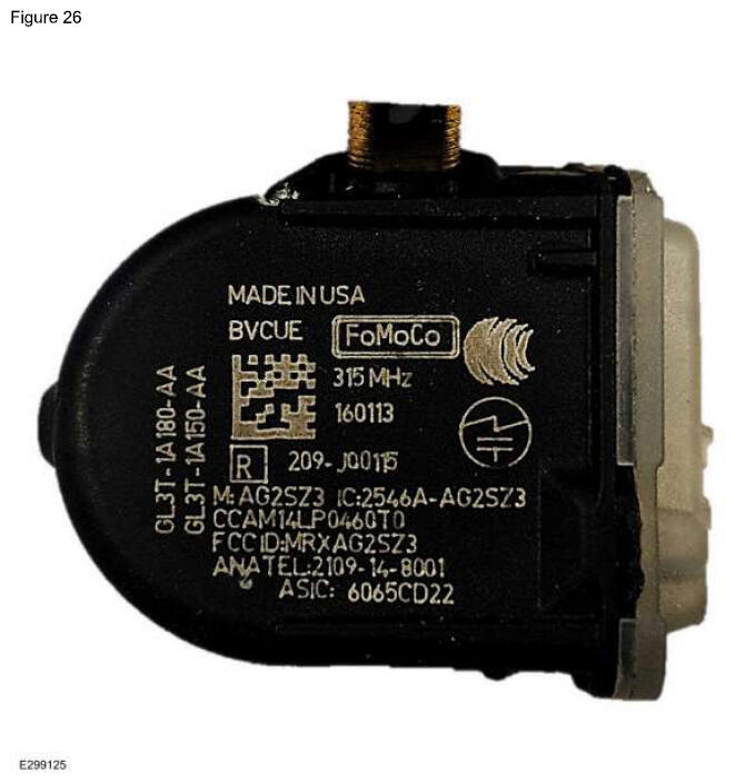
IDENTIFYING CORRECT FORD OE SENSOR (GL3TI FARADAY) FOR A PARTICULAR VEHICLE (FIGURE 26)
2 - GL3T-1A180-**
PARTS INFORMATION
| Engineering Part Number |
Description |
| GL3T-1A180-AA |
315 MHz Faraday |
| GL3T-1A180-CA |
433 MHz Faraday |
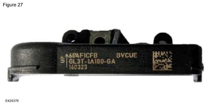
IDENTIFYING CORRECT FORD OE SENSOR (GL3TI POTTED FARADAY) FOR A PARTICULAR VEHICLE (FIGURE 27)
2 - GL3T-1A180-**
PARTS INFORMATION
| Engineering Part Number |
Description |
| GL3T-1A180-GA |
315 MHz Faraday - High Speed Valve |
| GL3T-1A180-GB |
315 MHz Faraday - High Speed Valve |
| GL3T-1A180-HA |
433 MHz Faraday |
| GL3T-1A180-HB |
433 MHz Faraday |
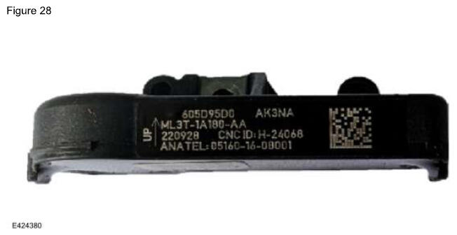
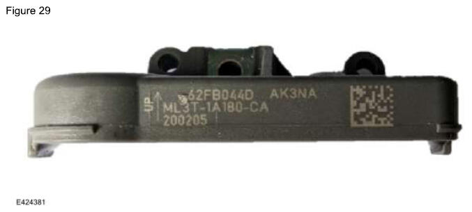
IDENTIFYING CORRECT FORD OE SENSOR (ML3TI POTTED FARADAY) FOR A PARTICULAR VEHICLE (FIGURES 28-29)
3 - ML3T-1A180-**
PARTS INFORMATION
| Engineering Part Number |
Description |
| ML3T-1A180-AA |
315 MHz Potted Faraday |
| ML3T-1A180-CA |
433 MHz Potted Faraday (Grey Enclosure) |
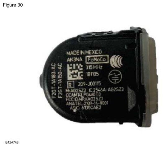
IDENTIFYING CORRECT FORD OE SENSOR (F2GTI FARADAY) FOR A PARTICULAR VEHICLE (FIGURE 30)
4 - F2GT-1A180-**
PARTS INFORMATION
| Engineering Part Number |
Description |
| F2GT-1A180-AA |
315 MHz Faraday - Low Speed Valve |
| F2GT-1A180-AB |
315 MHz Faraday - Low Speed Valve |
| F2GT-1A180-AC |
315 MHz Faraday - Low Speed Valve |
| F2GT-1A180-AD |
315 MHz Faraday - Low Speed Valve |
| F2GT-1A180-AE |
315 MHz Faraday - Low Speed Valve |
| F2GT-1A180-EA |
433 MHz Faraday - Low Speed Valve |
| F2GT-1A180-EB |
433 MHz Faraday - Low Speed Valve |
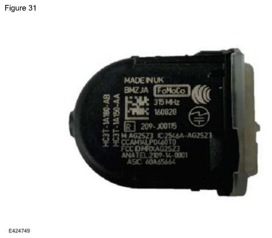
IDENTIFYING CORRECT FORD OE SENSOR (HC3TI FARADAY) FOR A PARTICULAR VEHICLE (FIGURE 31)
5 - HC3T-1A180-**
PARTS INFORMATION
| Engineering Part Number |
Description |
| HC3T-1A180-AA |
315 MHz Faraday - High Speed Valve |
| HC3T-1A180-AB |
315 MHz Faraday - High Speed Valve |
| HC3T-1A180-AC |
315 MHz Faraday - High Speed Valve |
| HC3T-1A180-AD |
315 MHz Faraday - High Speed Valve |
| HC3T-1A180-AE |
315 MHz Faraday - High Speed Valve |
| HC3T-1A180-GA |
315 MHz Faraday - High Speed Valve |
| HC3T-1A180-GB |
315 MHz Faraday - High Speed Valve |
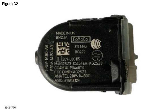
IDENTIFYING CORRECT FORD OE SENSOR (FR3VI BOLT-ON FARADAY) FOR A PARTICULAR VEHICLE (FIGURE 32)
6 - FR3V-1A180-**
PARTS INFORMATION
| Engineering Part Number |
Description |
| FR3V-1A180-AA |
315 MHz Faraday - Bolt-On Valve |
| FR3V-1A180-AB |
315 MHz Faraday - Bolt-On Valve |
| FR3V-1A180-AC |
315 MHz Faraday - Bolt-On Valve |
| FR3V-1A180-CC |
433 MHz Faraday - Bolt-On Valve |
| FR3V-1A180-GB |
315 MHz Faraday - Bolt-On Valve E-Coated Washer |
| FR3V-1A180-HB |
433 MHz Faraday - Bolt-On Valve E-Coated Washer |
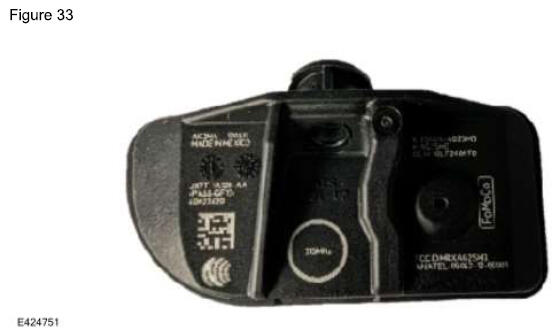
IDENTIFYING CORRECT FORD OE SENSOR (JX7TI MHSSI) FOR A PARTICULAR VEHICLE (FIGURE 33)
7 - JX7T-1A180-**
PARTS INFORMATION
| Engineering Part Number |
Description |
| JX7T-1A180-AA |
315 MHz MHSSI - High Speed Valve |
| JX7T-1A180-EA |
315 MHz MHSSI - Low Speed Valve |
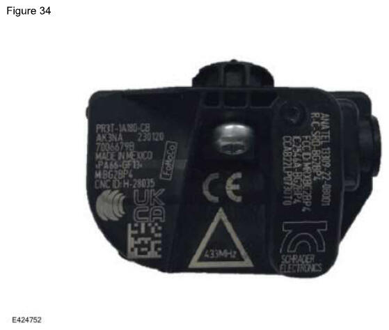
IDENTIFYING CORRECT FORD OE SENSOR (PR3TI BURNELL) FOR A PARTICULAR VEHICLE (FIGURE 34)
8 - PR3T-1A180-**
PARTS INFORMATION
| Engineering Part Number |
Description |
| PR3T-1A180-AB |
315 MHz Burnell - Low Speed Valve |
| PR3T-1A180-CB |
433 MHz Burnell - High Speed Valve |
| PR3T-1A180-EB |
315 MHz Burnell - Bolt-On Valve |
| PR3T-1A180-GB |
433 MHz Burnell - Bolt-On Valve |
| PR3T-1A180-KB |
433 MHz Burnell - Low Speed Valve #2 |
| PR3T-1A180-MB |
433 MHz Burnell - Low Speed Valve |
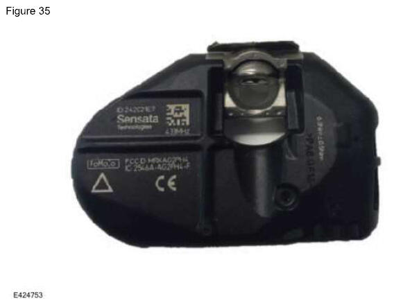
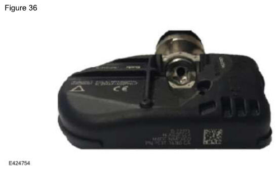
IDENTIFYING CORRECT FORD OE SENSOR (PC3TI STEEL CARCASS) FOR A PARTICULAR VEHICLE (FIGURES 35-36)
9 - PC3T-1A180-**
PARTS INFORMATION
| Engineering Part Number |
Description |
| PC3T-1A180-CA |
433 MHz Steel Carcass Production Steel Wheel Valve (Bent Brass) |
| PC3T-1A180-GB |
433 MHz Steel Carcass Production Alloy Wheel Valve |
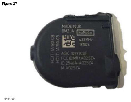
IDENTIFYING CORRECT FORD OE SENSOR FOR TRAILER TPMS (FIGURE 37)
10 - HC3T-1A180-**
PARTS INFORMATION
| Engineering Part Number |
Description |
| HC3T-1A180-CA |
433 MHz Trailer Sensor |
| HC3T-1A180-CB |
433 MHz Trailer Sensor |
| HC3T-1A180-CC |
433 MHz Trailer Sensor |
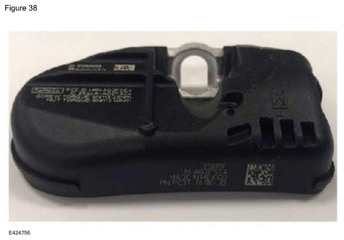
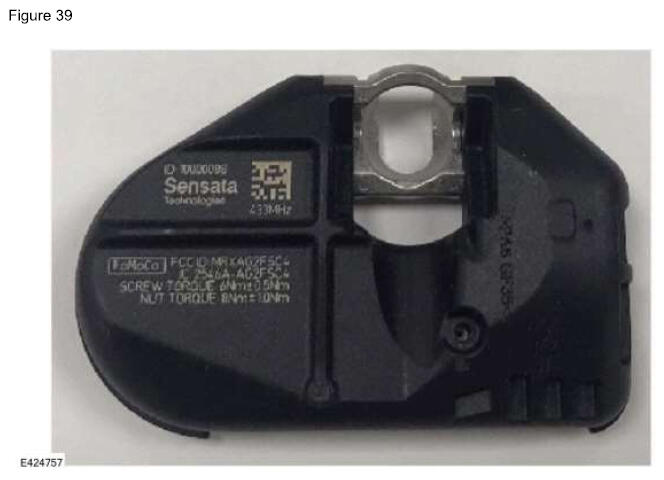
IDENTIFYING CORRECT FORD OE SENSOR FOR STEEL CARCASS TRAILER TPMS (FIGURES 38-39)
11 - PC3T-1A180-**
PARTS INFORMATION
| Engineering Part Number |
Description |
| PC3T-1A180-JB |
433 MHz Trailer Steel Carcass Sensor |
TPMS IDENTIFICATION CHART (FIGURE 40)
The numbers in this chart identify the type of sensors for each vehicle program. The numbers are in the upper left corner of the tables in Figures 25-39.
Figure 40 - TPMS Identification Chart
| Model |
2015 |
2016 |
2017 |
2018 |
2019 |
2020 |
2021 |
2022 |
2023 |
2024 |
2025 |
| Aviator |
|
|
|
|
|
|
7 |
7 |
7 |
8 |
8 |
| Bronco |
|
|
|
|
|
|
3 |
3 |
3 |
3 |
8 |
| Bronco Sport |
|
|
|
|
|
|
4 |
4 |
4 |
4 |
8 |
| Continental |
|
|
4 |
4 |
4 |
4 |
4 |
|
|
|
|
| C-Max |
|
|
1 |
1 |
|
|
|
|
|
|
|
| Corsair |
|
|
|
|
|
7 |
7 |
7 |
7 |
7 |
7 |
| EcoSport |
|
|
|
4 |
4 |
4 |
4 |
|
|
|
|
| Edge |
4 |
4 |
5 |
5 |
2,5 |
2,4 |
3,4 |
3,4 |
3,4 |
3,4 |
|
| Escape |
1 |
1 |
1 |
1 |
1 |
7 |
7 |
7 |
7 |
7 |
7 |
| E-Series |
1 |
1 |
1 |
1 |
1 |
2,6 |
2,6 |
2,3 |
2,3 |
2,3 |
8 |
| Expedition |
1 |
1 |
1 |
2,5 |
2,5 |
2 |
2 |
2,3 |
3 |
3 |
8 |
| Explorer/Police Interceptor Utility |
1 |
4 |
4 |
4 |
4 |
7 |
7 |
7 |
7 |
8 |
8 |
| F-150 |
4 |
2 |
2 |
2 |
2 |
2 |
3 |
3 |
3 |
3 |
3 |
| F-150 Lightning |
|
|
|
|
|
|
3 |
3 |
3 |
3 |
3 |
| F-150 Raptor |
|
2 |
2 |
2 |
2 |
2 |
3 |
3 |
3 |
3 |
3 |
| F-Super Duty |
1 |
1 |
5,6 |
2, 5,6 |
2, 5,6 |
2, 5,6 |
2,6 |
2, 3,6 |
3,6 |
3,6 |
6,8 |
| Fiesta |
1 |
1 |
1 |
4 |
4 |
4 |
|
|
|
|
|
| Flex |
1 |
1 |
1 |
1 |
1 |
|
|
|
|
|
|
| Focus |
1 |
1 |
1 |
1 |
|
|
|
|
|
|
|
| Ford GT |
|
|
* |
* |
* |
* |
* |
* |
|
|
|
| Fusion |
1 |
1 |
5 |
5 |
5 |
5 |
|
|
|
|
|
| Maverick |
|
|
|
|
|
|
4 |
4 |
4 |
4 |
8 |
| MKC |
1 |
1 |
1 |
5 |
5 |
|
|
|
|
|
|
| MKS |
1 |
1 |
|
|
|
|
|
|
|
|
|
| MKT |
1 |
1 |
1 |
1 |
1 |
|
|
|
|
|
|
| MKX |
4 |
4 |
2,4 |
2,4 |
|
|
|
|
|
|
|
| MKZ |
1 |
1 |
5 |
5 |
5 |
5 |
|
|
|
|
|
| Mustang |
4 |
4 |
4 |
4 |
4 |
4 |
4 |
4 |
4 |
4 |
8 |
| Mustang Mach-E |
|
|
|
|
|
|
|
4 |
4 |
4 |
8 |
| Mustang SVT |
** |
6 |
6 |
6 |
6 |
6 |
6 |
6 |
6 |
6 |
6 |
| Nautilus |
|
|
|
|
2,5 |
2,4 |
3,4 |
3,4 |
3,4 |
3,4 |
3,4 |
| Navigator |
1 |
1 |
1 |
2,5 |
2,5 |
2 |
2 |
2,3 |
3 |
3 |
8 |
| Ranger |
|
|
|
|
5 |
5 |
3 |
3 |
3 |
3 |
8 |
| Taurus/Police Interceptor Sedan |
1 |
1 |
1 |
1 |
1 |
|
|
|
|
|
|
| Transit |
1 |
1 |
1 |
1 |
1 |
6,7 |
6,7 |
6,7 |
6,7 |
6,7 |
6,8 |
| Transit Connect |
|
1 |
1 |
1 |
4 |
4 |
4 |
4 |
4 |
4 |
8 |
| Trailer TPMS Kit |
|
|
10 |
10 |
10 |
10 |
10 |
10 |
10, 11 |
11 |
11 |
Figure 40 legend
| * |
Ford GT uses a specialized black anodized bolt-on valve. The part number prefix for this is HG7Z. |
| ** |
Mustang SVT uses a bolt-on valve. The part number prefix for this is DR3V. |
TPMS SENSOR NON-WARRANTABLE ISSUES
With the variety of sensors that come equipped on Ford/Lincoln vehicles, make sure the sensor type is carefully identified and the correct mount and dismount procedure is used for each type of TPMS
sensor. Damage to the TPMS
sensor is identifiable with each part being reviewed prior to warranty approval. The sensor may not respond for a number of non-warrantable reasons that require the replacement of the sensor. They are:
- Damage due to improper tire mount and/or dismount procedure
- Damage due to being run on a flat or severely under-inflated tire
- Damage due to impact
- Damage due to improper removal of the valve stem
- Sensor replaced due to the use of a tire sealant
- Pressure port clogged due to the use of sealants or other materials (rubber, grease, balancing materials, etc.)
- Damage due to mounting on wheels not designed to accommodate TPMS sensors properly
Other Non-Warrantable Conditions:
- Wrong frequency parts
- Wrong sensor type (both Ford and non-Ford sensors)
- Over-repair (replacing the whole sensor vs replacing a valve)
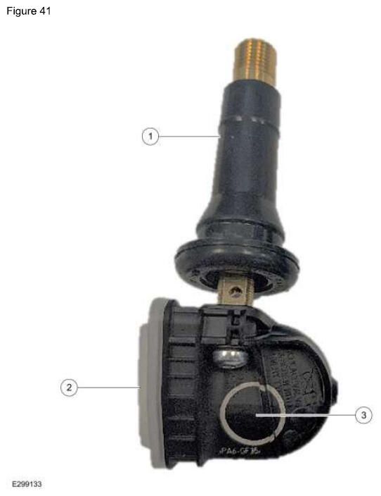
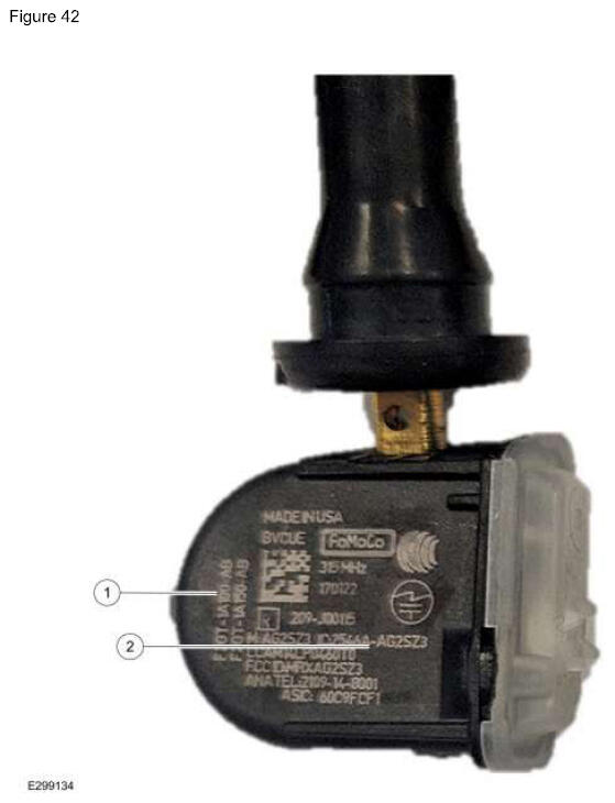
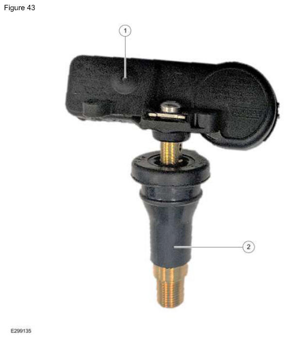
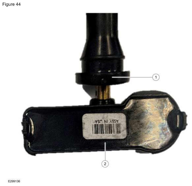
GOOD PART EXAMPLES (FIGURES 41-44)
ITEM DESCRIPTION
| Item |
Description |
| 1 |
Undamaged valve stem |
| 2 |
Undamaged ladder area/lid |
| 3 |
Undamaged sensor body |
ITEM DESCRIPTION
| Item |
Description |
| 1 |
Correct Ford Part Number |
| 2 |
Undamaged Sensor Body |
ITEM DESCRIPTION
| Item |
Description |
| 1 |
Pressure Port Not Obstructed |
| 2 |
Undamaged Valve Stem |
ITEM DESCRIPTION
| Item |
Description |
| 1 |
Undamaged Valve Stem |
| 2 |
Undamaged Potting |
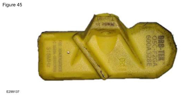
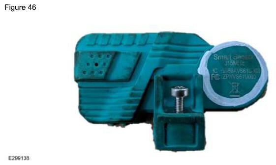
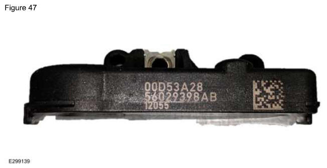
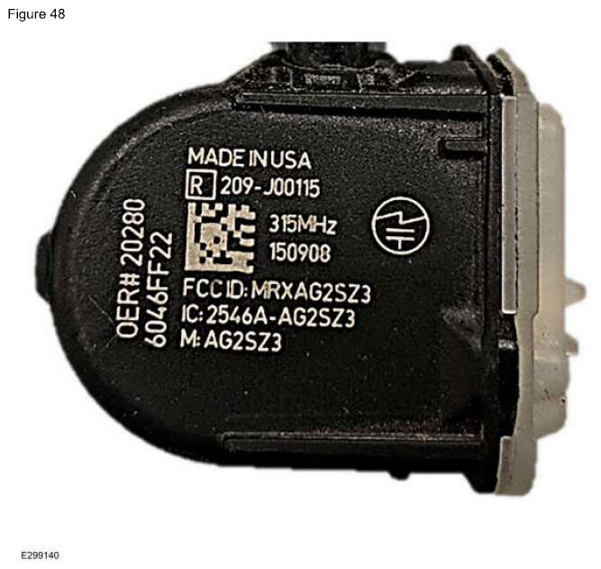
NON-FORD PART EXAMPLES (CHARGEBACKS)
Different colors. North American units all use black parts. (Figures 45-46)
No Ford part number (Figures 47-48)
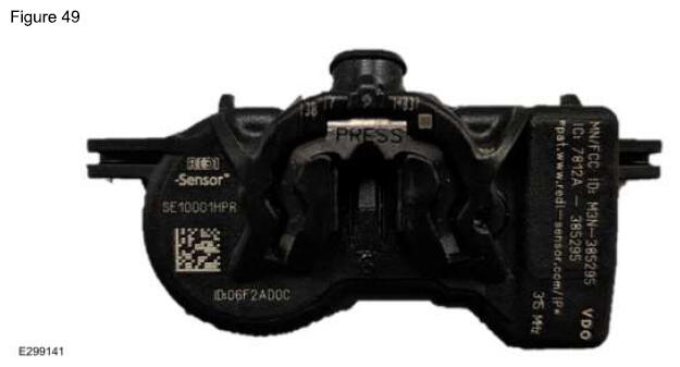
Different shapes.
NOTE:
North American units all use either the Edison or the Faraday profile. (Figure 49)
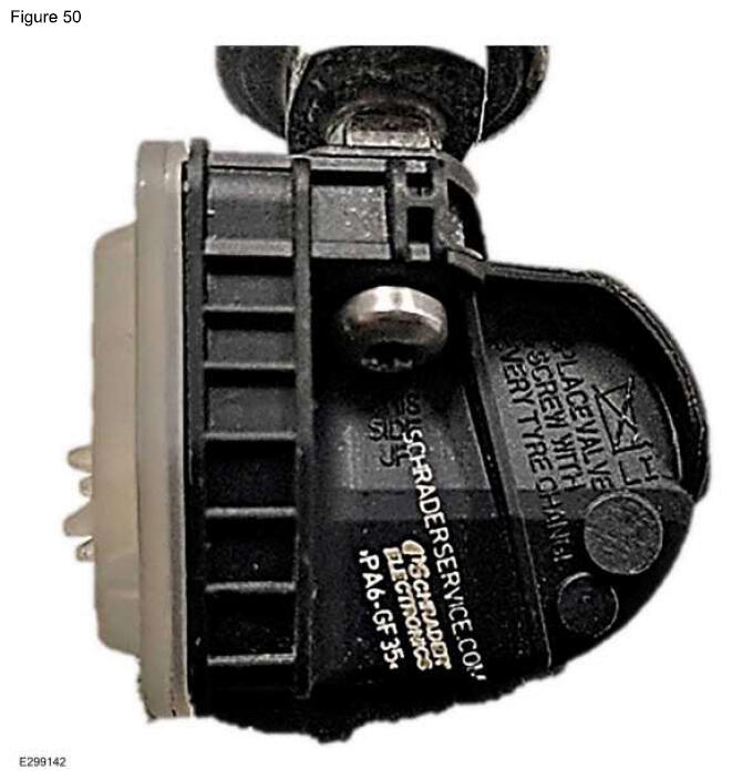
Aftermarket Branding.
NOTE:
This could include branding such as EzSensor, Redi, and Schrader (Figure 50)
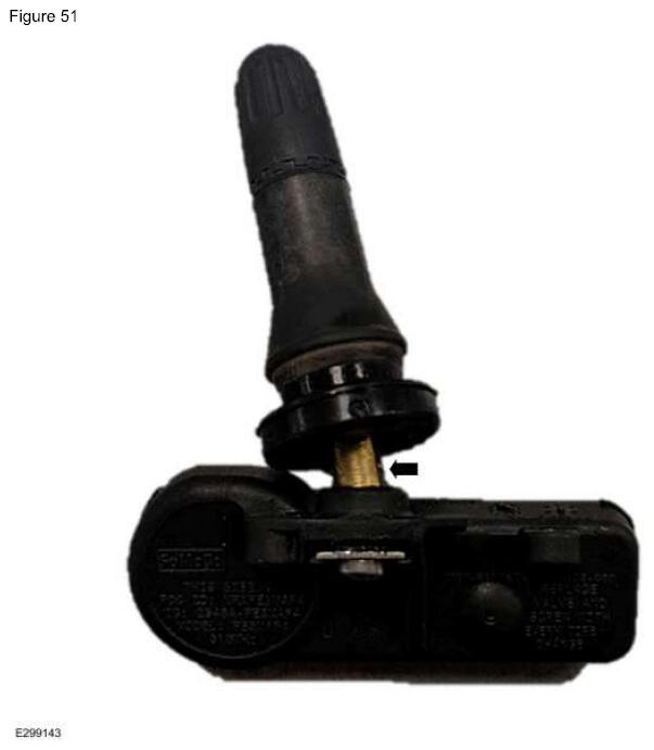
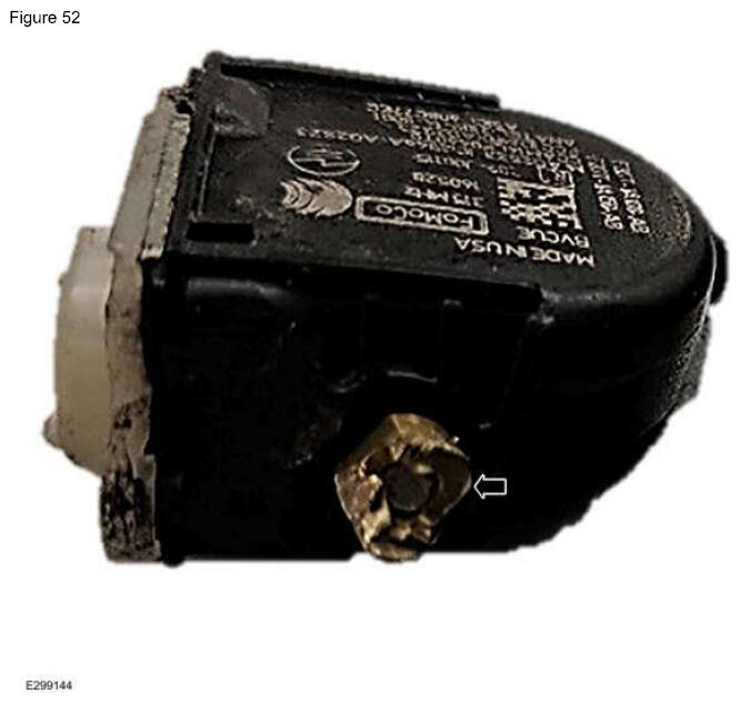
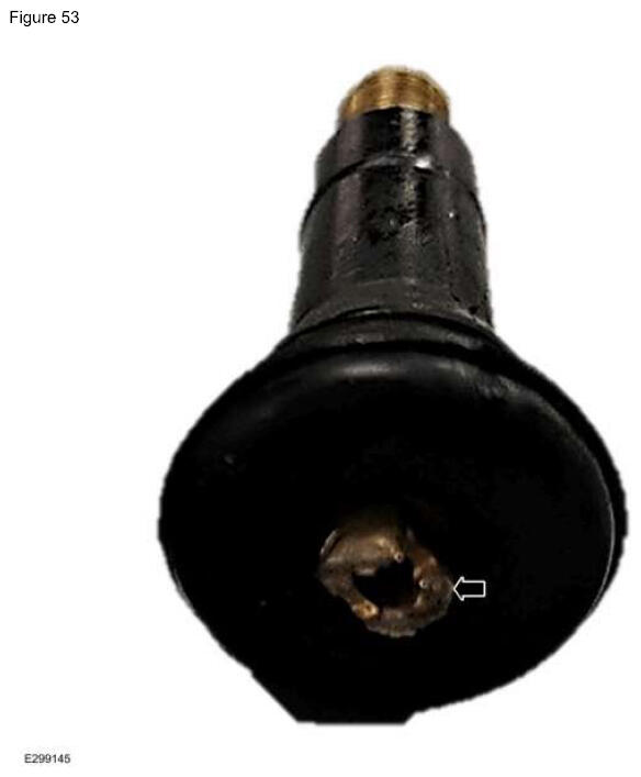
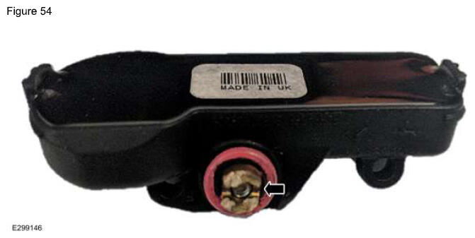
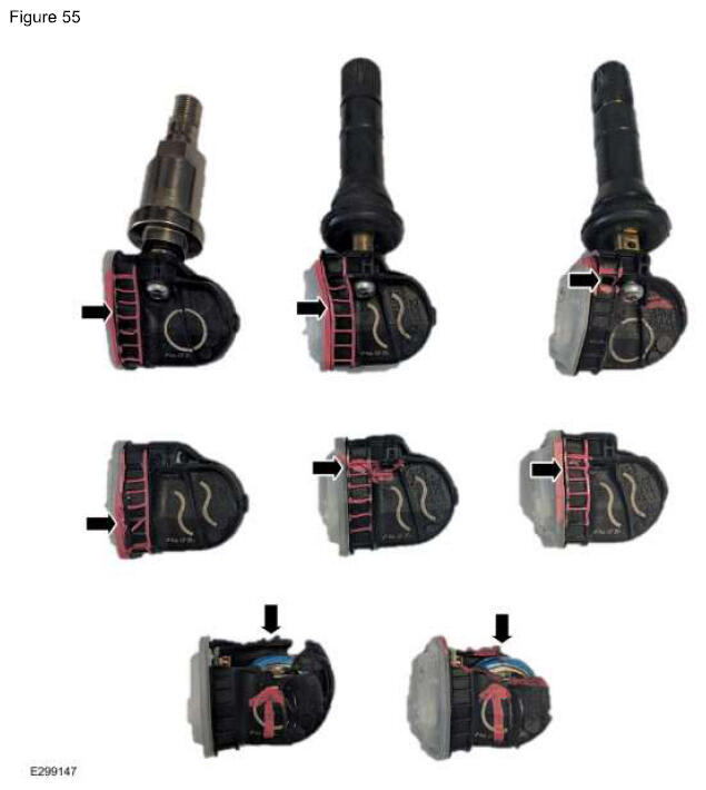
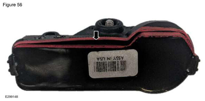
SENSOR DAMAGE EXAMPLES (CHARGEBACKS)
Damaged valve stems (Figures 51-54)
Damage to the sensor body (Figures 55-56)
AVOIDING CHARGEBACKS
Wrong Part Details:
Things To Look For:
- Does the sensor build date make sense for the model year of the vehicle? For example, if the sensor was built in 2019, it would not make sense to see this on a vehicle that is newer than the date on the sensor. It should be fairly close to the vehicle's production date.
- Does the part number match what is listed in the catalog?
- Is the part the correct frequency? Unless it is a trailer sensor the frequency for North American vehicles should be 315 MHz.
Wrong Part Returned:
This is the most common chargeback when it comes to TPMS
. A few ways to avoid being charged back for this can include:
- Include the sensor ID, build date, and part number within the technician comments. This will make sure that the part attached to the 700 tag is the part that is returned.
- Verify the correct sensor using the parts catalog or this document. Sending back an Edison sensor instead of a Faraday sensor will result in a chargeback and vice versa.
- Include a second copy of the 700 tag in the shipping box/envelope if attaching to the outside package.
- Do not return a sensor that was made in 2009 for a vehicle that was made in 2019, as an example. If the sensor is over a year old compared to the vehicle build date then it is highly likely it is the wrong part.
- Do not send back non-Ford TPMS
sensors or other Ford parts.
- Do not send back 433 MHz sensors if the vehicle has over 1,000 miles. North American vehicles do not use this frequency (trailer TPMS
does).
Sensor Damaged:
This is the second most common chargeback:
- The easiest way to avoid being charged back for this is to properly dismount the tire. Also making sure to remove the sensor from the valve stem before attempting to remove the valve stem.
- If a sensor is damaged, and it is not caused by the plant, then do not send it back. Plant damage is easily determined upon review.
- Do not send back a sensor if the valve stem was damaged.
- Any defacing or intentional damaging of the part will result in a chargeback.
Over Repair:
This is the third most common chargeback. Examples of this include:
- Replacing the entire sensor kit for a leaky valve. Order the proper valve kit to replace the valve.
- Replacing the entire sensor kit for a cracked or blemished wheel.
- Replacing all 4 sensors due to a BCM
or RTM
issue.
- Replacement BCM
s do not have the TPMS
IDs stored in them. Non-functional RTM
s will cause TPMS faults.