Description And Operation: Headlamps
Overview
The headlamp system consists of:
- Headlamp assemblies
- Ballasts (HID only)
- Headlamp switch (integrated into the FLM)
- Multifunction switch
- BCM
- SCCM
The headlamp system is a dual-beam pattern system. It consists of a single replaceable headlamp bulb in each headlamp assembly. The vehicle may come equipped with halogen or HID bulbs. The park/turn and side marker lamps are integrated into the headlamp assembly.
System Operation
System Diagram
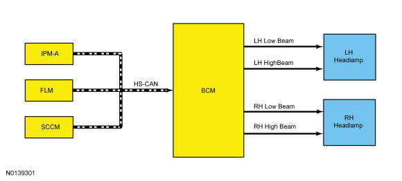
Network Message Chart BCM Network Message Chart
| Broadcast Message | Originating Module | Message Purpose |
|---|---|---|
| Headlamp switch status | FLM | Indicates the headlamp switch position (or fault) to the BCM. When the position is indicated as the HEADLAMPS ON (or a fault), the BCM provides voltage to the parking lamps and headlamps. |
| High beam_flash-to-pass request | SCCM | Indicates to the BCM a request for the high beams or flash-to-pass. |
SCCM Network Message Chart
| Broadcast Message | Originating Module | Message Purpose |
|---|---|---|
| Automatic high beam request | IPM-A | Indicates to the SCCM a request for the high beams based on the IPM-A camera input. |
Battery Saver
To save battery voltage, the BCM provides automatic shut-off of the interior and exterior lamps after a time-out period when the ignition is off. The BCM monitors the ignition state and input from the RKE system to determine when to energize or de-energize the battery saver relay and to shut the power off to the lamps. A timer in the BCM starts when:
- the ignition changes to OFF,
- any door or liftgate becomes ajar while the ignition is off,
- an UNLOCK button of the RKE transmitter is pressed while the ignition is off,
- a valid keypad code is entered while the ignition is off,
- or the courtesy lamp switch (integrated into the FLM) is used to turn the courtesy lamps on while the ignition is off.
When 10 minutes have elapsed, the BCM automatically shuts off voltage to the lamps. The timer restarts (voltage is restored if the BCM is in battery saver mode) if:
- the ignition transitions out of OFF,
- any door or liftgate becomes ajar,
- the UNLOCK button of the RKE transmitter is pressed,
- a valid keypad code is entered,
- the courtesy lamp switch is pressed.
Low Beams
The headlamp switch is integrated into the FLM. The FLM monitors the headlamp switch position and sends a headlamp switch status message over the communication network to the BCM to indicate the headlamp switch status (position or a fault with the headlamp switch).
If the BCM detects a fault from the headlamp switch or loses communication with the FLM, the BCM turns the parking lamps and headlamps on and keeps them on until the battery saver feature times out (Refer to Headlamps , Battery Saver). If either situation occurs, the BCM cannot be ruled immediately as being at fault. This is normal behavior of the BCM design as a fault has been detected with the inputs from the headlamp switch.
When the BCM receives input requesting the headlamps on, it supplies voltage to the headlamp bulbs (halogen headlamps) or the ballasts (HID headlamps) within each headlamp assembly.
Vehicles with halogen headlamps use single filament bulbs.
Vehicles with HID headlamps utilize ballasts to provide the necessary voltage to illuminate the HID bulbs.
The BCM also provides an overload protection of the low beam output circuits. When an excessive current draw is detected, the BCM disables the affected low beam circuit driver. REFER to Multifunction Electronic Modules , Field Effect Transistor (FET) Protection.
High Beams
The SCCM monitors the multifunction switch for a high beam or flash-to-pass request. When the multifunction switch is in the HIGH BEAM or FLASH-TO-PASS position, the SCCM sends a high beam_flash-to-pass request message to the BCM over the communication network indicating the request.
When the low beams are on and the BCM receives a request for high beams, the headlamps remain powered and the shutter within each headlamp is activated. This changes the headlamp beam pattern to illuminate a greater distance.
The BCM also provides an overload protection of the high beam output circuits. When an excessive current draw is detected, the BCM disables the affected high beam circuit driver. REFER to Multifunction Electronic Modules , Field Effect Transistor (FET) Protection.
Automatic High Beams
The automatic high beam system uses a camera mounted to the interior rear view mirror to monitor surrounding traffic conditions and high beam usage. The automatic high beam feature is active only when the headlamp switch is in the AUTOLAMPS position.
The automatic high beams can be enabled/disabled in the IPC message center through the following process.
- From the message center main menu, use the up and down arrow buttons to scroll to and select Settings. Press the OK button.
- Use the up and down arrow buttons to scroll to and select Vehicle. Press the OK button.
- Use the up and down arrow buttons to scroll to and select Auto High Beam. Press the OK button.
- Use the up and down arrow buttons to scroll to and select either On or Off. Press the OK button.
During nighttime driving, the automatic high beam system automatically turns the high beams on if it is dark enough and no other traffic is present. When the system detects an approaching vehicle's headlamps or a preceding vehicle's rear lamps, the system turns off the high beams. When the approaching vehicle's headlamps or the preceding vehicle's rear lamps are no longer detected, the high beams automatically turn back on.
Flash-To-Pass
The SCCM monitors the multifunction switch for a high beam or flash-to-pass request. When the multifunction switch is in the HIGH BEAM or FLASH-TO-PASS position, the SCCM sends a high beam_flash-to-pass request message to the BCM over the communication network indicating the request.
When the low beams are off and the flash-to-pass is requested, the headlamp bulbs and the shutters are activated for approximately 0.5 second. When the low beams are on and the flash-to-pass is requested, the shutters within the headlamps are activated as long as the multifunction switch is held in the FLASH-TO-PASS position.
Component Description
Headlamp Assembly
The headlamp assembly has an integrated solenoid activated shutter which changes the headlamp beam pattern when activated. The solenoid and shutter are not serviceable separately from the headlamp assembly. The headlamp assembly is provided power on independent circuits for the low beams and the high beams.
On vehicles equipped with HID headlamps, a ballast is located within each headlamp assembly.
Lamp Assembly Condensation
Exterior lamps are vented to accommodate normal changes in pressure. Condensation can be a natural by-product of this design. When moist air enters the lamp assembly through the vents, there is a possibility that condensation can occur if the temperature is cold. When normal condensation occurs, a thin mist forms on the interior of the lens. The thin mist eventually clears and exits through the vents during normal operation. The amount of time it takes to clear the lens of acceptable mist varies with ambient humidity and lamp types. Normal condensation clears from any lamp in 48 hours under dry conditions.
Do not replace a lamp assembly with acceptable levels of condensation such as:
- presence of thin mist (no streaks, drip marks or droplets are present)
- fine mist covers less than 50% of the lens
Examples of unacceptable moisture (usually caused by a lamp housing leak):
- water puddling inside the lamp
- large water droplets, drip marks or streaks present on the interior of the lens
Ballast
There is a ballast located within each headlamp assembly. They are provided power at all times. The ballasts provide high voltage to the HID bulbs when a voltage signal is detected from the BCM.
Front Lighting Control Module (FLM)
The FLM monitors the headlamp switch (integrated into the FLM. When the FLM detects the headlamp switch is in the HEADLAMP ON position (or a fault with the headlamp switch), it sends a message over the communication network to the BCM, indicating the headlamp switch position or a fault with the headlamp switch input.