Reversing Lamps
Overview
The reverse lamp system consists of:
- Reverse lamps
- PCM
- BCM
When the transmission is placed in REVERSE, the reversing lamps are illuminated. The reversing lamps are located within the rear lamp assemblies.
System Operation
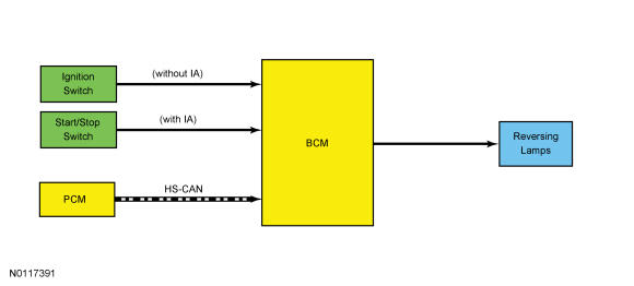
System Diagram
Network Message Chart Network Message Chart
| Broadcast Message | Originating Module | Message Purpose |
|---|---|---|
| Selector lever (PRNDL) status | PCM | Indicates the gear selector lever position to the BCM. When the selector lever is in REVERSE and the ignition in RUN, the BCM provides voltage to the reversing lamps. |
Reversing Lamps - Automatic Transaxle
When the transmission is in REVERSE, the PCM sends a selector lever (PRNDL) status message over the communication network to the BCM indicating the transmission is in REVERSE. The BCM provides voltage to the reversing lamps when it receives the message that the transmission is in REVERSE and the ignition is in RUN.
The BCM also provides an overload protection of the reversing lamp output circuits. When an excessive current draw is detected, the BCM disables the affected reversing lamp circuit driver. REFER to REFER to Multifunction Electronic Modules .