Instrument Panel Upper Section: Removal
WARNING:
Before beginning any service procedure in this service information, refer to SAFETY WARNINGS
- 1.
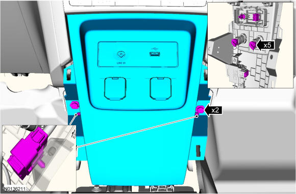
All vehicles except Police Interceptor. Remove the front floor console. Refer to Console - Front, Floor .
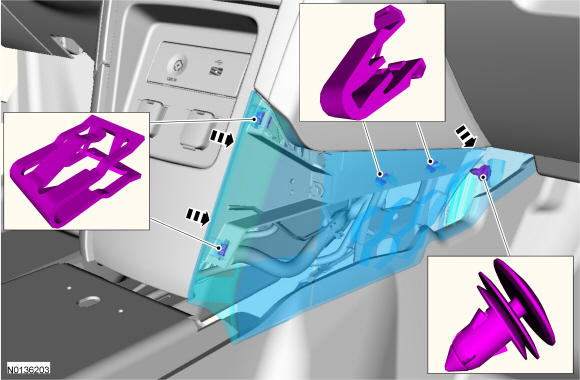
- 2.NOTE: RH side shown in illustration, LH side similar.
Police Interceptor vehicles only. Remove the LH side and RH side center lower instrument panel finish panels.
- 4.
Remove the LH and RH scuff plate trim panels. REFER to Interior Trim and Ornamentation .
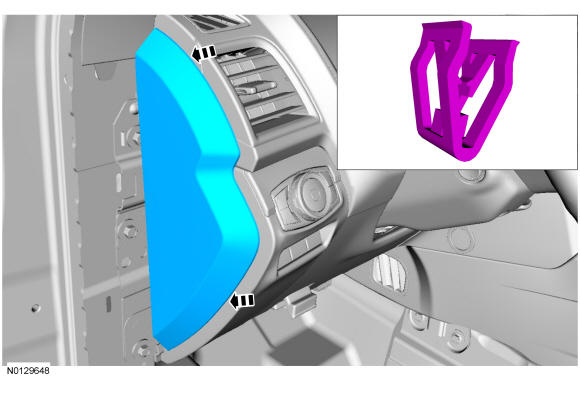
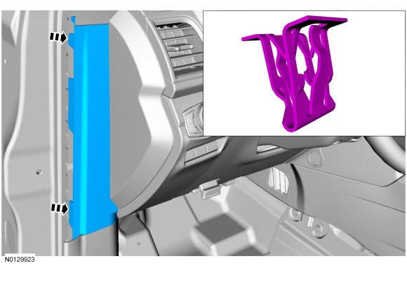
- 6.NOTE: LH side shown in illustration, RH side similar.
Remove the LH and RH instrument panel side trim panels.
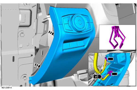
- 7.NOTE: LH side shown in illustration, RH side similar.
Remove the LH and RH cowl side trim covers.
- 8.
Remove the steering column. REFER to Steering Column .
- 10.
Remove the IPC. REFER to Instrumentation, Message Center, and Warning Chimes .
- 13.
Remove the hood release handle bolt and remove the hood release handle.- 1.
To install, tighten to 5 Nm (44 lb-in).
- 1.
- 14.
Remove the glove compartment door. Refer to Glove Compartment .
- 17.
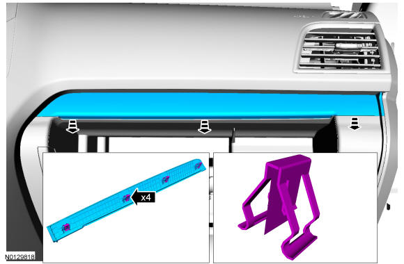
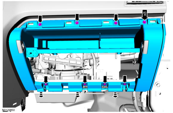
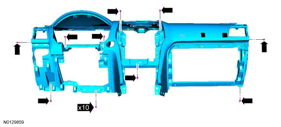
Remove the 8 screws and remove the glove compartment close out.- 1.
To install, tighten to 2.5 Nm (22 lb-in).
- 1.
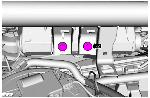
- 18.NOTE: Apply threadlock to the passenger side air bag to in-vehicle cross beam bolts prior to installation.
Remove the 2 passenger side air bag to in-vehicle cross beam bolts.
- 1.
To install, tighten to 9 Nm (80 lb-in).
- 1.
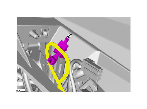
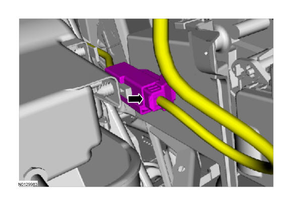
- 19.NOTE: LH side shown in illustration, RH similar.
Disconnect the RH and LH passengers side air bag electrical connectors.
- 20.
Remove the ACM. REFER to Information and Entertainment Systems - Premium Plus - ACM. Remove the FDIM. REFER to Information and Entertainment Systems - Premium Plus - FDIM.
- 21.
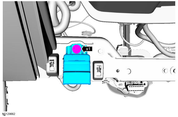
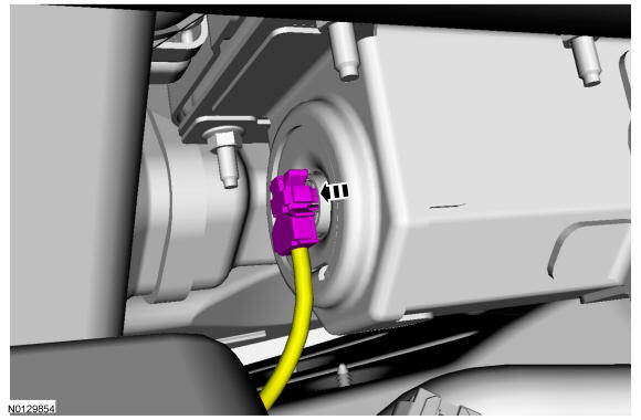
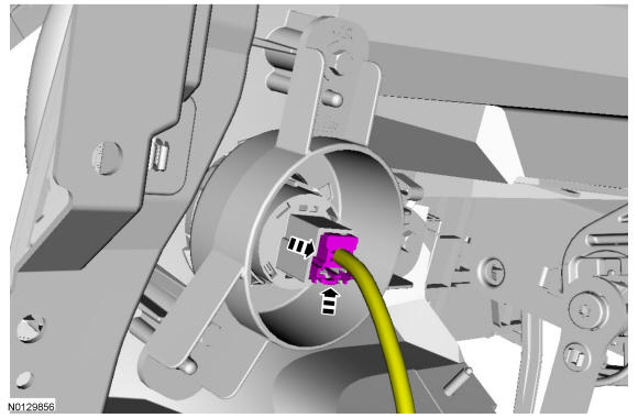
Disconnect the ignition switch electrical connector or the push button start switch electrical connector.
- 22.
If equipped, remove the instrument panel speaker and grille as an assembly.- 1.
Disconnect the electrical connector.
- 1.
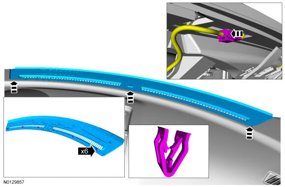
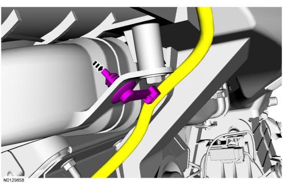
- 25.
Gently pull the RH side of the instrument panel upper section rearward and detach the defroster grille electrical harness push pin from the HVAC duct.