Conventional Ignition Switch - Without Intelligent Access (IA): Notes
Overview
The conventional ignition switch is controlled by the ignition lock cylinder and key. The ignition lock cylinder and ignition switch are connected mechanically, turning the lock cylinder places the switch into the desired position. The available ignition switch positions are:
- OFF
- ACC
- RUN
- START
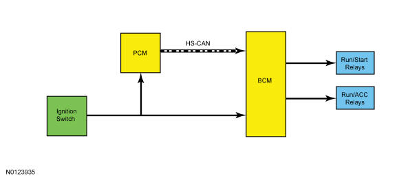
When placed in any position other than OFF, the ignition switch provides voltage inputs to the BCM-B. The BCM-B distributes this voltage to other modules and vehicle systems through the RUN/ACC and the RUN/START relays. The microprocessor internal to the BCM-B broadcasts an ignition mode network message over the MS-CAN and the HS-CAN.
System Operation
System Diagram
OFF
When the ignition switch is turned to the OFF position, the BCM-B sends an "engine off" message to the other modules over the HS-CAN.
Acc
When the BCM-B receives the ACC voltage input from the ignition switch it activates the RUN/ACC bus and the RUN/ACC relay, providing ignition accessory power to the various vehicle systems and modules. The BCM-B also sends out the ignition mode message on the MS-CAN and the HS-CAN.
RUN
When the BCM-B receives the RUN voltage input from the ignition switch it activates the RUN/ACC bus, the RUN/START bus, the RUN/ACC relay and the RUN/START relay, providing ignition power to the various vehicle systems and modules. The BCM-B also sends out the ignition mode message on the MS-CAN and the HS-CAN.
Start
When the BCM-B receives the START voltage input from the ignition switch it activates the RUN/START bus and the RUN/START relay, providing ignition power to the various vehicle systems and modules. The BCM-B also sends out the ignition mode message on the MS-CAN and the HS-CAN.
The ignition switch START circuit is also hard wired to the PCM. The PCM uses the ignition switch START input to determine when to activate the starter motor relay. REFER to Starting System , Starting System.