Message Center: Notes
Overview
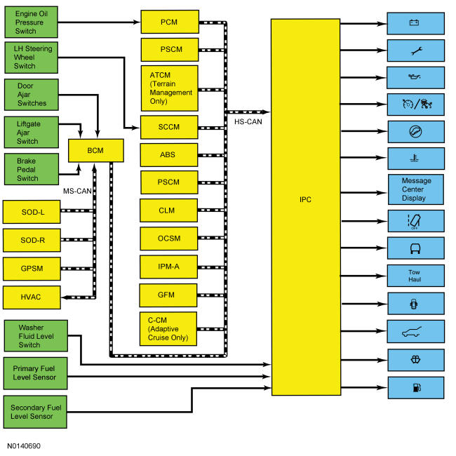
The message center is an integral part of the IPC that receives and acts upon much of the same information that is input and used to operate the IPC gauges, indicators, and warning indicators. The message center uses both hardwired and the network based inputs to receive information.
The message center functionality is controlled through the message center switch (part of the LH steering wheel switch), which is hardwired to the SCCM through input and return circuits.
Whenever conditions are present that require a warning message, the message center replaces the last selected display with the new warning display. Once the message is reset or cleared, the message center returns to the last selected display. If multiple warnings are present, the message center displays each warning for approximately 4 seconds. Warning messages are also generally associated with other observable outputs of the IPC (gauges, indicators and message center indicators). For example, when the BCM detects a low brake fluid condition, the BCM sends the IPC a request to illuminate the brake warning indicator and a request to display the LOW BRAKE FLUID message in the message center. This allows the message center to be a more informative supplement to the IPC gauges and indicators.
Another function of the message center is to display message center warning indicators. Similar to the interaction between the message center and the standard warning indicators, the message center often displays a warning message and the message center warning indicator at the same time. For example, if the PCM detects low engine oil pressure, the PCM sends a request to the IPC to illuminate the low oil pressure message center indicator and to display LOW OIL PRESSURE in the message center. If multiple warnings are present requiring multiple message center warning indicator displays, the message center cycles or rotates through the displays in the same manner the message center cycles the text messages.
System Warning Messages
The system warning messages alert the operator to possible problems or malfunctions in the vehicle operating systems. System warning messages may be stand-alone messages but are often associated with another form of indication such as a gauge, an indicator or message center indicator. The message center displays the last selected feature if there are no additional warning messages. Once a warning message has been displayed, the message must be acknowledged to allow full functionality of the message center. Press the OK button to acknowledge and clear the warning message.
Refer to the Owner's Literature for a complete list of the messages.
System Operation
System Diagram
-
Network Message Chart
| Broadcast Message | Originating Module | Message Purpose |
|---|---|---|
| Adaptive cruise control follow mode display | C-CM | Input used to display the adaptive cruise control follow status and operate the cruise control message center indicator. |
| Adaptive cruise control gap setting | C-CM | Input used to provide the adaptive cruise control gap setting display. |
| Adaptive cruise control memory enabled | C-CM | Input used to determine whether the driver has selected normal cruise control or adaptive cruise control to enable the adaptive cruise control displays. |
| Adaptive cruise control message display | C-CM | Input used to display the adaptive cruise control is not available message resulting from a system malfunction. |
| Adaptive cruise control monitor error | BCM | Input used to display the adaptive cruise control system malfunction warning message. |
| Adaptive cruise control request denied | C-CM | Used for adaptive cruise control messages. |
| Adaptive cruise control service required request | C-CM | Input used to provide the adaptive cruise control system malfunction warning message. |
| Adaptive cruise control set speed display | PCM | Input used for adaptive cruise control messages. |
| Adaptive cruise control warning display | C-CM | Input used for adaptive cruise control messages. |
| AWD lock status | PCM | Input used for the 4WD component of the powertrain malfunction (wrench) indicator and the 4WD fault message display. |
| AWD display request | PCM | Input used for the 4WD state display messages. |
| Ambient air temperature | BCM | Combined messages for outside air temperature status and outside air temperature updated information for the outside air temperature display. |
| Ambient air temperature fault reporting | BCM | Input used to display all dashes (- - - -) in the outside air temperature display area due to faulty data being received. |
| Auxiliary switch display | Generic Function Module (GFM) | Input use to display the status of the police auxiliary switch status. |
| Brake fluid level low | BCM | Brake fluid level status for displaying the low brake fluid level warning message. |
| Brake warning indicator request | BCM | Input used for parking brake applied message. |
| Camera status | IPM-A | Input used to display the camera malfunction warning message. |
| Charging system status | PCM | Provides the charging system indication request to control the charging system message center warning indicator. |
| Collision mitigation by braking monitor error | BCM | Input used to display the forward collision system malfunction warning message. |
| Cross traffic information | SOD-L and SOD-R | Input used to provide cross traffic warning messages. |
| Cruise control mode | PCM | Input used for adaptive cruise control messages. |
| Cruise control status | PCM | Input used for adaptive cruise control message center indicator and messages. |
| Cruise control override | PCM | Input used for adaptive cruise control messages. |
| Driver alert warning | IPM-A | Input used for the display of the driver alert message center displays. |
| Drivers door ajar status | BCM | Provides the door ajar request to display the driver door ajar message and illuminate the door ajar message center warning indicator. |
| EPAS failure | PSCM | Input required for the service power steering message. |
| Engine coolant temperature | PCM | Engine temperature data used for the engine over-temperature message center warning indicator. |
| Engine coolant temperature fault reporting | PCM | Input used to determine the quality of the engine temperature data input for the engine over-temperature message center warning indicator. |
| Engine oil life percent | PCM | Input used for the oil life display. |
| Engine overheat failsafe mode | PCM | Input used for the fail safe status component of the engine over-temperature message center warning indicator. |
| Engine service required | PCM | Input used for the ETC component of the powertrain malfunction (wrench) indicator. |
| Forward collision warning deny | C-CM | Input used to display the forward collision system not available message resulting from a system malfunction. |
| Forward collision radar sensor status | C-CM | Input used to display the radar sensor not aligned and the radar sensor blocked warning messages. |
| Forward collision mitigation by braking service required | C-CM | Input used to display the forward collision system malfunction warning message. |
| Fuel fill inlet | PCM | Input required for the display of the fuel fill inlet message. |
| Fuel flow | PCM | Input used for average fuel flow, DTE and trip fuel displays. |
| GPS compass direction | GPSM | Provides compass heading data (converted from MS-CAN to HS-CAN in the BCM) for the compass display. |
| Hill descent mode status | ABS | Provides the hill descent mode request for display of the hill descent messages. |
| Hill start assist display | ABS | Input required to display the hill start assist display. |
| Ignition status | BCM | Ignition RUN, START and accessory states required for the IPC operating modes and fault reporting. |
| Immobilize indicator | BCM | Input used to provide the starting system fault message for the PATS. |
| Intelligent access system status | BCM | Input used to control the warning messages displayed for IA. |
| Lane assist display | IPM-A | Input used to display lane keeping aid messages. |
| Lane assist feature configuration | IPM-A | Input used for the lane assist system configuration or customer settings of the system. |
| Lane assist hands off display | IPM-A | Input used to display the hands off the steering wheel message. |
| Lane assist status | IPM-A | Input used to display the lane departure warning system status message when the system is unavailable. |
| Left rear door ajar status | BCM | Provides the door ajar request to display the left rear door ajar message and illuminate the door ajar message center warning indicator. |
| Liftgate ajar status | BCM | Provides the door ajar request to display the liftgate ajar message and illuminate the door ajar message center warning indicator. |
| MyKey ® key display | BCM | Input used to provide the MyKey ® key information for display messages related to MyKey ® key programming and setup. |
| Odometer count | PCM | Rolling count data used for the odometer and trip odometer. |
| OCS object entrapped message request | OCSM | Input used to display the remove objects near the passenger seat warning message. |
| Oil pressure warning | PCM | Provides the oil pressure switch status to control the low oil pressure message center warning indicator. |
| Park brake chime request | BCM | Input used to display the parking brake applied warning message |
| Passenger door ajar status | BCM | Provides the door ajar request to display the passenger door ajar message and illuminate the door ajar message center warning indicator. |
| Parking aid fault status | PAM | Input required for the display of the active park assist fault message. |
| Passenger rear door ajar status | BCM | Provides the door ajar request to display the right rear door ajar message and illuminate the door ajar message center warning indicator. |
| Power liftgate mode status | LTM | Input used to provide the power liftgate setup menu display (converted from MS-CAN to HS-CAN in the BCM). |
| Side detect information | SOD-L and SOD-R | Input used to provide CTA Blind Spot Information System (BLIS) sensor data for system state and system fault warning messages. |
| Steering wheel controls (cursor and OK button) | SCCM | Message center switch input from the LH steering wheel switch. |
| Terrain display request | ATCM | Provides the driver selected terrain display request. |
| Terrain mode | ATCM | Provides the actual terrain mode. |
| Tire pressure data | BCM | Inputs used to provide faulty messages received over the HS-CAN. |
| Tire pressure status | BCM | Inputs used to provide low tire warning messages. |
| Trailer sway configuration command | ABS | Provides the current configuration status in the ABS for the trailer sway feature. |
| Trailer sway event in progress | ABS | Provides trailer sway status request for display of the trailer sway warning message. |
| Transmission malfunction indicator request | PCM | Input used for the transaxle component of the powertrain malfunction (wrench) indicator. |
| Transmission shift mode | PCM | Input required for the tow haul and grade assist message center indicator. |
| Transport mode | BCM | Input used to indicate the vehicle is configured in transport mode for the cluster to power down items such as the PRNDL at key off to conserve the battery. |
Oil Change Minder
The message center provides an oil change minder to inform the driver that an oil change is required. The duration of the interval between oil changes is calculated in the PCM and varies due to driving conditions. The PCM assumes a base mileage of 16, 090 km (10, 000 mi) or 1 year for normal driving. However, this number is adjusted down for conditions such as high engine temperature, high engine Revolutions Per Minute (RPM), use of flex fuel and possibly low oil level. The PCM calculates and provides an engine oil life percent message to the IPC.
When the remaining oil life is between 1%-5%, the message center displays the change oil soon message. When the remaining oil life is at 0%, the message center displays the oil change required message.
Compass Display
The compass signal originates with the GPS antenna. No calibration or zone adjustment is available, as the compass heading is based on the GPS signal. Refer to the appropriate article for the procedure for information on the GPS signal.
Keypad Factory Code Display
The message center can display the original keypad factory code when requested. Refer to Handles, Locks, Latches and Entry Systems Without Intelligent Access (IA) or REFER to Handles, Locks, Latches and Entry Systems With Intelligent Access (IA) Description and Operation (D&O) for the procedure to display the keypad factory code.
Outside Air Temperature Display
The AAT sensor is hardwired to the PCM through separate input and return circuits. The PCM provides a reference voltage to the AAT sensor and monitors the change in voltage resulting from changes in resistance as determined by outside air temperature. The PCM messages the outside air temperature data to the HVAC module through the BCM. The HVAC filters the temperature data and sends the updated temperature status back to the BCM. The BCM in turn messages the outside air temperature in degrees Celsius (metric) to the IPC. When the Fahrenheit (English) display is selected by the driver, the IPC converts the Celsius to Fahrenheit and displays the temperature in the message center.
The HVAC module is programmed to update the messaged outside temperature data at different rates depending on several criteria to prevent false temperature displays due to a condition known as heat soaking. Heat soaking is where the outside air temperature is hotter in the location of the AAT sensor than the actual outside air temperature.
When the sensed outside temperature rises, the display updates slowly at varying rates based on vehicle speed. When the sensed outside temperature drops, the display updates more quickly following the drop experienced by the AAT sensor.
Powertrain Malfunction (Wrench) Message Center Indicator
The IPC receives the ETC, the transaxle and the 4WD status from the PCM.
When a fault condition exists in the ETC system, the PCM provides the IPC with the engine service required message to illuminate the powertrain malfunction (wrench) message center warning indicator.
When a fault condition exists in the transaxle, the PCM provides the IPC with the transmission malfunction indicator request to illuminate the powertrain malfunction (wrench) message center warning indicator.
When a fault condition exists in the 4WD system, the PCM provides the IPC with the AWD lock status message to illuminate the powertrain malfunction (wrench) message center warning indicator.
Charging System Message Center Warning Indicator
The charging system message center warning indicator is controlled by the IPC based upon data received from the BCM. The BCM receives the charging system status from the PCM. When a fault is detected in the charging system, the BCM sends the IPC a charging system status message to illuminate the charging system message center warning indicator. Refer to Charging System additional information on the charging system operation.
Cruise Control Message Center Indicator
On base cruise control vehicles, the IPC receives the cruise control status message from the PCM.
When the cruise control switch is placed in the ON position, the PCM sends the IPC a standby mode request through the cruise control status message and the IPC illuminates the cruise control indicator in gray. When the cruise control is engaged, the PCM sends a cruise control on request through the cruise control status message to the IPC and the IPC changes the cruise control indicator illumination from gray to green.
On vehicles equipped with adaptive cruise control, the IPC receives the adaptive cruise control follow mode display message from the C-CM.
When the cruise control switch is placed in the ON position, the C-CM sends the IPC a standby mode request through the adaptive cruise control follow mode display message and the IPC illuminates the cruise control indicator in gray. When the cruise control is engaged, the C-CM sends a cruise control on request through the adaptive cruise control follow mode display message to the IPC and the IPC changes the cruise control indicator illumination from gray to green.
Low Oil Pressure Message Center Warning Indicator
The engine oil pressure switch is hardwired to the PCM. The PCM provides the engine oil pressure status and engine Revolutions Per Minute (RPM) data to the Instrument Panel Cluster (IPC) over the HS-CAN communication bus. The IPC requires engine Revolutions Per Minute (RPM) above 500 Revolutions Per Minute (RPM) before the message center displays the low oil pressure message center indicator.
The PCM provides a reference voltage to the engine oil pressure switch when the ignition is in RUN. With the engine running and low or no oil pressure, the engine oil pressure switch remains open. The PCM detects no change in the reference voltage and provides the Instrument Panel Cluster (IPC) a request to illuminate the low oil pressure warning indicator. With the engine running and sufficient oil pressure, the engine oil pressure switch closes, pulling the reference voltage low. The PCM detects the low reference voltage and provides the Instrument Panel Cluster (IPC) a request to turn off the low oil pressure warning indicator.
The engine oil pressure switch is hardwired to the PCM. The IPC receives the oil pressure warning message and the engine Revolutions Per Minute (RPM) message from the PCM. With the KOEO, the IPC does not display the low oil pressure message center warning indicator until the engine is started and it receives the engine Revolutions Per Minute (RPM) message.
Engine Over-Temperature Message Center Warning Indicator
The PCM uses the CHT sensor to measure the engine temperature. The IPC receives the engine coolant temperature data message from the PCM. The IPC requires 2 basic messaged inputs to control the engine over-temperature message center warning indicator. The first is the engine coolant temperature data message. The second is an engine overheat mitigation message. When the engine temperature reaches 121 C ° (250 F °), or when the PCM sends the engine coolant temperature data message, the IPC illuminates the engine over-temperature message center warning indicator.
Grade Assist Message Center Indicator
The IPC receives the grade assist on/off status from the PCM. When the grade assist function is selected off, the PCM sends the transmission shift mode message to the IPC to illuminate the grade assist message center indicator.
Low Fuel Message Center Indicator
The IPC uses fuel level, running average fuel economy, odometer counts and fuel flow data to calculate the DTE. The low fuel message center indicator is controlled using the calculated DTE. When the DTE display is 120 km (75 miles) (with a MyKey ® programmed key) or 80 km (50 miles) (with an administrator key) to empty or less, the IPC illuminates the low fuel message center indicator.
Low Washer Fluid Message Center Indicator
The low washer fluid level sensor is hardwired to the IPC through a single signal circuit. The low washer fluid sensor is grounded through a separate ground circuit. The IPC provides a battery reference voltage to the washer fluid level switch. When the washer fluid is low, the washer fluid level switch closes to ground, pulling the reference voltage low. When the IPC detects the washer fluid input pulled low, it illuminates the low washer fluid level message center warning indicator.
Door Ajar Message Center Indicator
The IPC receives the door ajar status for the LF, RF, LR, RR and the liftgate ajar switches from the BCM. When the IPC receives a driver door, passenger door, left rear door, passenger rear door or liftgate ajar status message from the BCM that one or more doors are open or ajar, the IPC illuminates the appropriate door ajar message center warning indicator.
Check Fuel Fill Inlet Message Display
The PCM monitors the fuel tank evaporative emission system for significant leaks that occur following refueling of the vehicle. Once the PCM detects a fuel vapor leak, the PCM sends a fuel fill inlet message to the IPC to display the CHECK FUEL FILL INLET message. The PCM only sets a fault code following a successful cruise test, which is initiated when the vehicle is driven at a steady speed above 64.36 km (40 mi) for a duration of approximately 4-5 minutes. If the PCM is unable to successfully run the cruise test, the IPC does not receive the fuel fill inlet message and the CHECK FUEL FILL INLET message remains off.
Shift To Park Message Display
The Instrument Panel Cluster (IPC) displays SHIFT TO PARK when the vehicle is turned off with the shifter out of the PARK (P) position or when the ignition is ON with the shifter out of park and the driver door is ajar or open on vehicles with Intelligent Access (IA). The IPC provides a reference voltage to the park detect switch through the park detect signal, or input circuit. The IPC provides the transaxle park status to the BCM.
When the selector lever is out of the PARK (P) position, the park detect switch remains open to ground leaving the reference voltage high to the IPC. The IPC sends a park status message to the BCM, indicating that the selector lever is not in PARK (P). The BCM monitors the ignition state and when the ignition is OFF with the selector lever out of PARK (P), the BCM sends the IPC an intelligent access system status message to display the SHIFT TO PARK message display.
Hill Descent Control Message Display
The hill descent control system maintains vehicle speed on a downhill grade at operating speeds between 3.2 km/h (2 mph) and 32.2 km/h (20 mph). The system goes into standby mode on a flat or uphill terrain. The system deactivates at speeds above 64.4 km/h (40 mph). During periods of sustained use, the hill descent control system may automatically deactivate in order to cool the braking system.
When the hill descent control switch is pressed, a ground signal is sent to the PCM. The PCM then sends a message to the ABS module requesting system activation. The ABS module uses inputs from the RCM and wheel speed sensors to determine the mode of operation.
The IPC receives the hill descent mode status message from the ABS module. The message center also displays hill descent control messages to inform the driver they have entered or exited various states of the hill descent control function.
Auxiliary Switch Menu Display - Police Package
The IPC receives the auxiliary switch status from the Generic Function Module (GFM). When an auxiliary switch is turned on, the Generic Function Module (GFM) sends the police auxiliary switch display message to the IPC, which displays a switch image in the message center, changing the display from gray to blue to indicate the status.
Lane Departure Warning System Display
The departure warning system display is controlled by data sent to the IPC from the IPM-A. When the lane departure warning system is enabled, the IPC displays an overhead view of a vehicle inside of lane markers in the LH message center screen next to the fuel gauge.
The lane departure warning system displays right and left lane markers and arrows that change color to indicate the vehicle's position within the roadway lane markers. The lane departure warning system can be turned off by the driver. When the lane departure warning system is turned off, the lane departure warning system display is turned off in the LH IPC display screen. Refer to Lane Departure Warning for a complete description of the lane departure warning system and the associated lane marker color changes/warnings.