Removal And Installation - All Wheel Drive
REMOVAL
- Remove the rear spring link. Refer to LINK, SPRING, REMOVAL AND INSTALLATION .
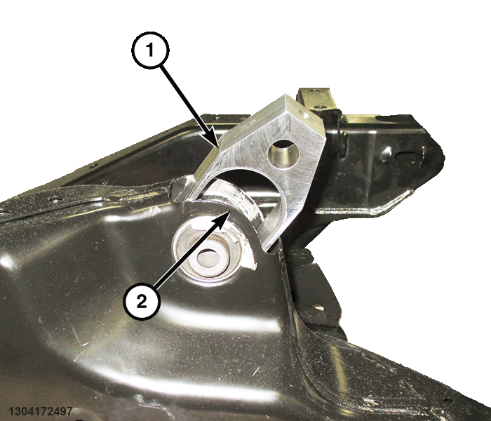
- As an installation reference, carefully mark the location of the isolator requiring removal on crossmember (around isolator can flange) using a marker or crayon.
Do not use a scratch awl to mark location.
- Install the Support, spring link bushing 2074223130
into the crossmember (2) over the isolator and seat fully.NOTE:
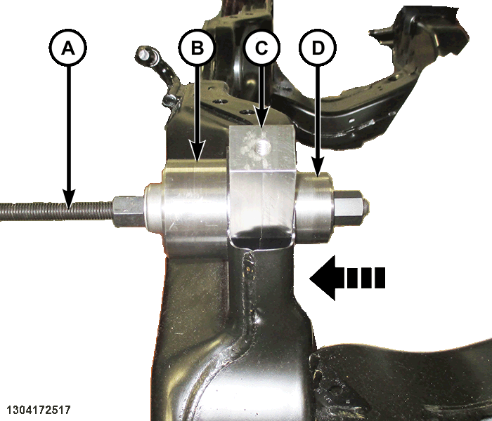
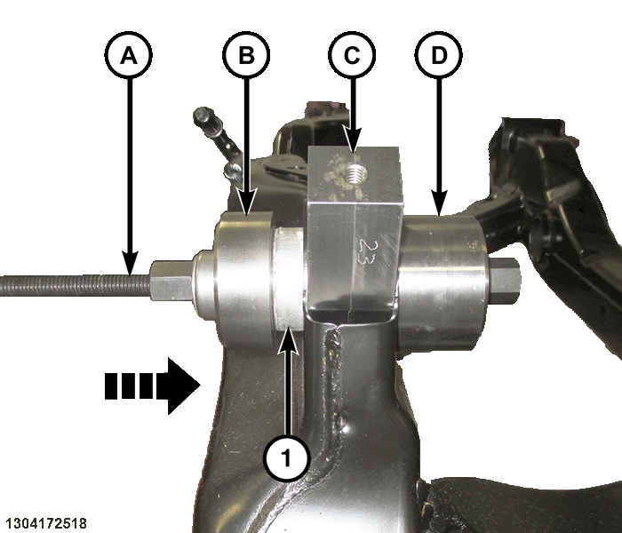
Prior to using special tools, lubricate Pressing Tool (special tool #2026900170, Kit, Pressing Tool) (E) threads to provide ease of use and promote tool longevity.
- Assemble tools over isolator crossmember assembly as shown:
- (special tool #2026900170, Kit, Pressing Tool)
- Receiver, spring link bushing 2074221130
- Support, spring link bushing 2074223130
- Driver, spring link bushing - removal 2074222130
- Tighten Pressing Tool (A), pressing bushing out of crossmember and remove all tools.
INSTALLATION
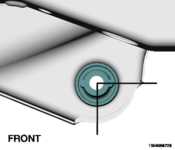
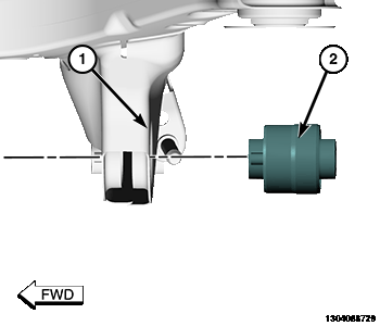
- Position isolator (2) on crossmember isolator bore (1).
- Aligning isolator can flange with reference marks applied during removal.
- Assemble tools over isolator crossmember assembly as shown:
- (special tool #2026900170, Kit, Pressing Tool)
- Driver, spring link bushing - installation 2074220130
- Support, spring link bushing 2074223130
- Receiver, spring link bushing 2074221130
- Tighten the Pressing Tool (special tool #2026900170, Kit, Pressing Tool) (E) screw-drive, pressing isolator into crossmember. Install the isolator until the Driver, spring link bushing - installation 2074220130 contacts the surface of the crossmember.
- Remove tools.
- Install the rear spring link. Refer to LINK, SPRING, REMOVAL AND INSTALLATION .
NOTE:
Prior to using special tools, lubricate Pressing Tool assembly (special tool #2026900170, Kit, Pressing Tool) (1) threads to provide ease of use and promote tool longevity.
NOTE:
A mixture of soap and water may be used to aid installation of the isolator.