Removal And Installation
REMOVAL
- Raise and support the vehicle. Refer to HOISTING, STANDARD PROCEDURE
.
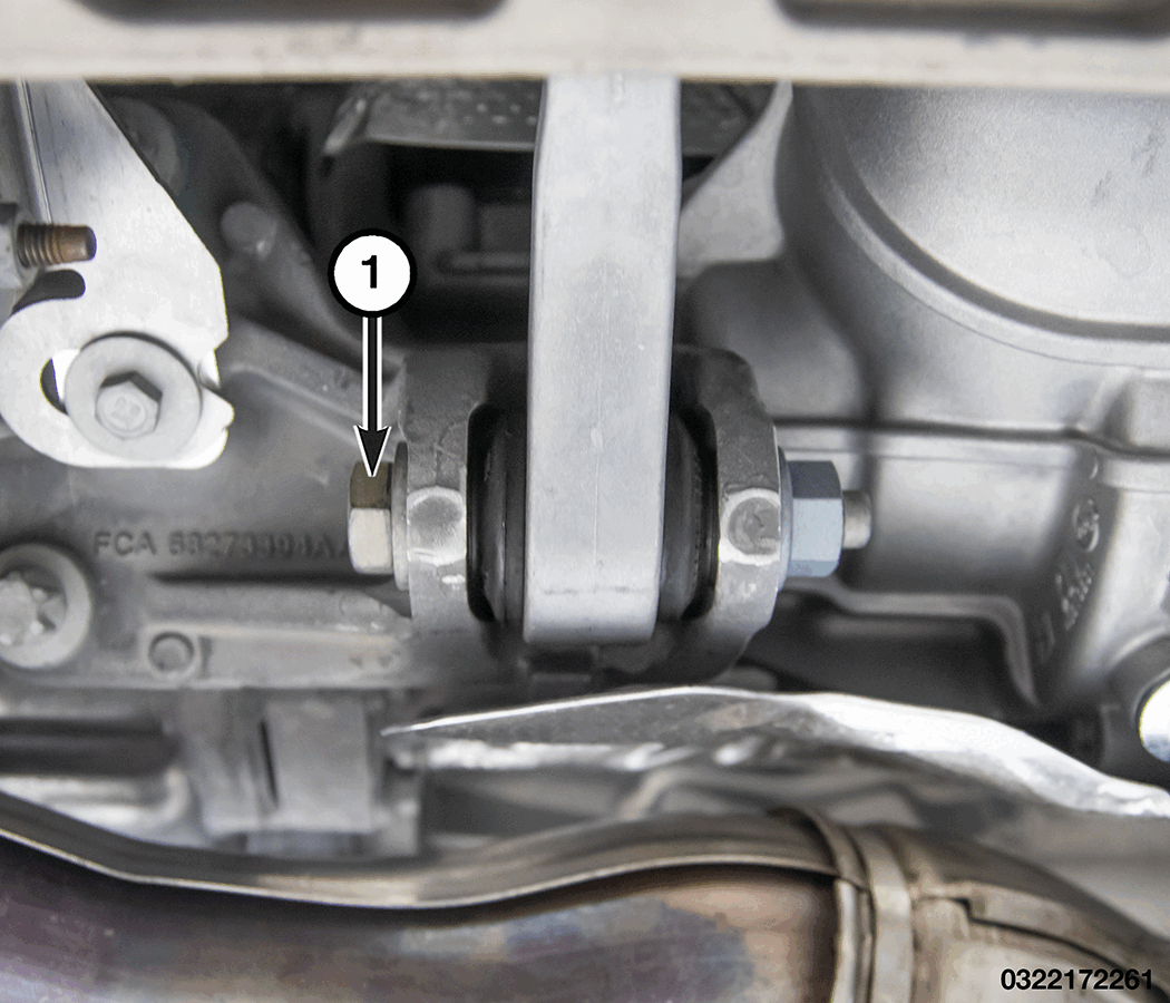
- Remove the fastener (1) from the rear torque strut.
- Use a jack stand to rotate the front of the drivetrain upwards.
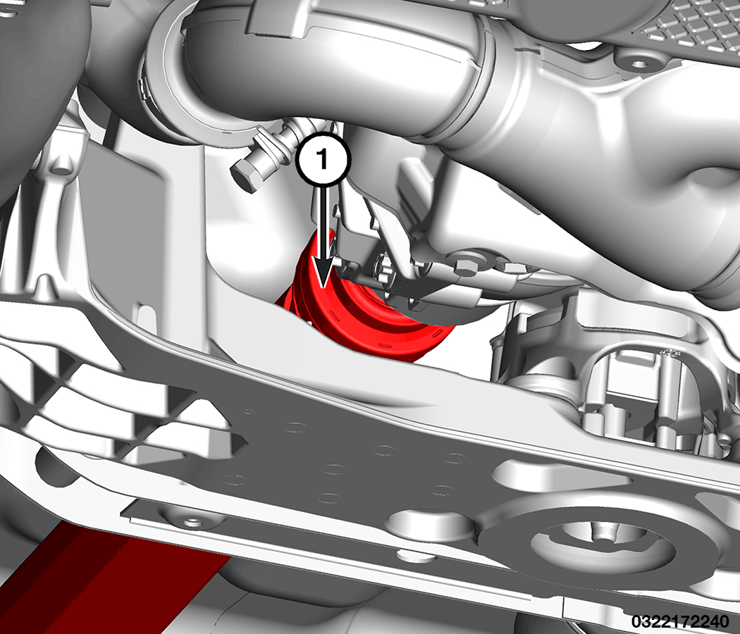
- Install the Tool 2075300030 to the propeller shaft (1) and use a prybar to separate the joint.
- Remove and DISCARD
the retention ring on the output shaft of the PTU.
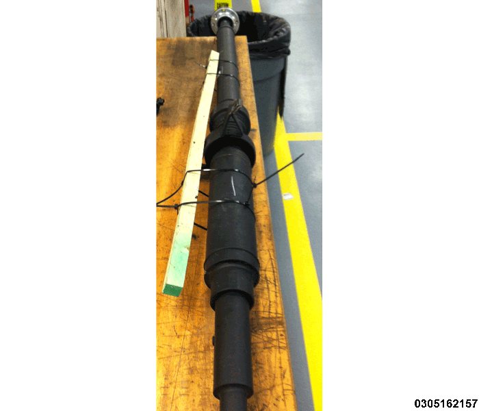
- Using a long piece of wood or similar, fasten it to the propeller shaft with several cable ties in order to keep the propeller shaft from over-articulating during removal and installation.
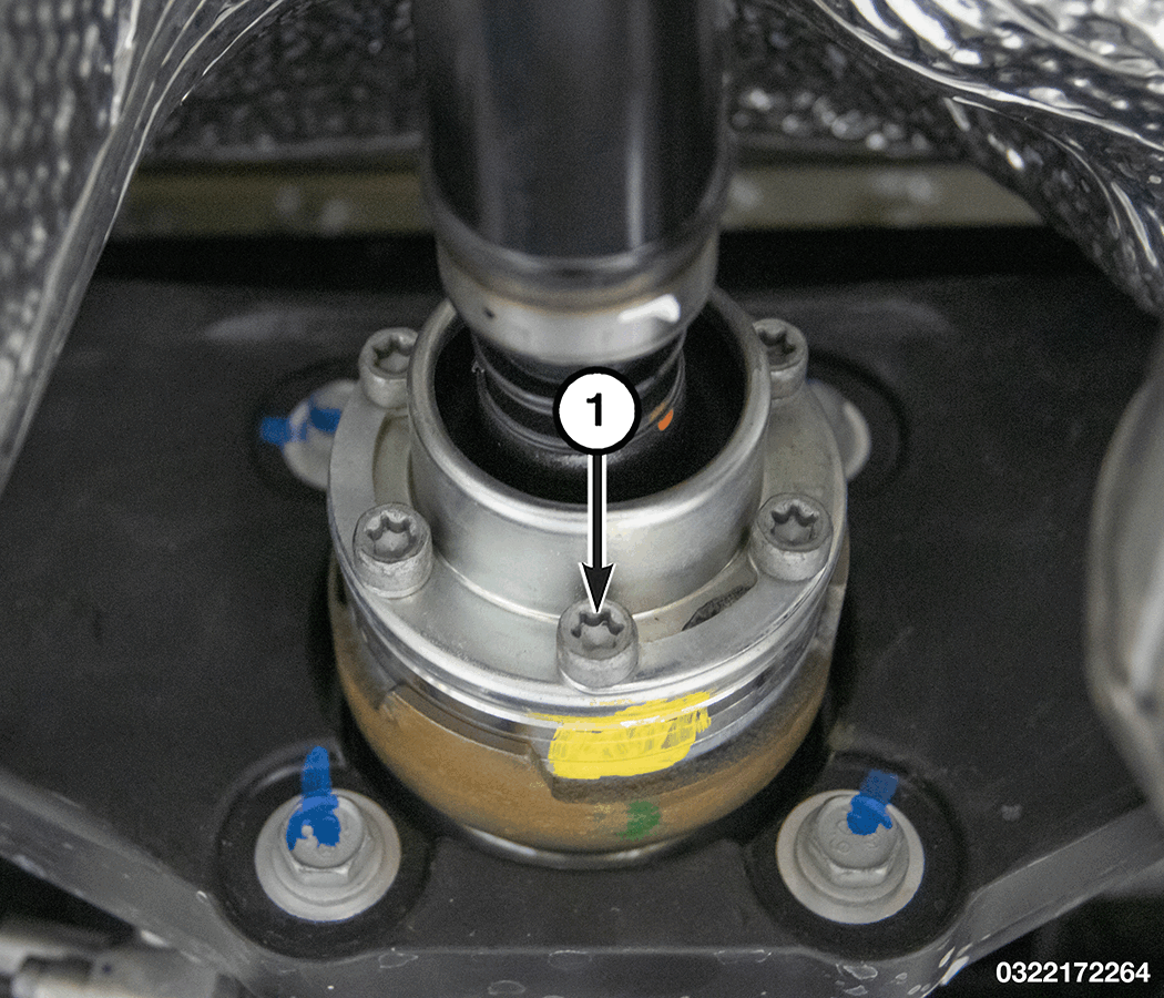
- Create a index mark on the propeller shaft and pinion flange.
- Remove and DISCARD
the propeller shaft bolts (1). Separate the propeller shaft from the pinion flange.
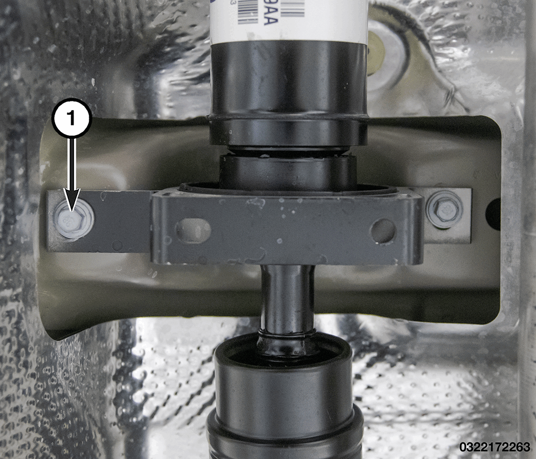
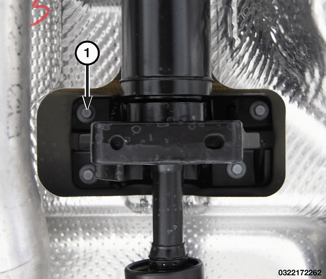
- Remove the fasteners (1) from the propshaft support bearing and separate from the body.
- Remove the fasteners (1) from the propshaft support bearing and separate from the body.
- Remove the propeller shaft from the vehicle.
INSTALLATION
- Position the propeller shaft in the vehicle.
- Position the propeller shaft support bearing to the body. Install the fasteners (1) and tighten to the proper torque specifications. Refer to TECHNICAL SPECIFICATIONS .
- Position the propeller shaft support bearing to the body. Install the fasteners (1) and tighten to the proper torque specifications. Refer to TECHNICAL SPECIFICATIONS .
- Join the propeller shaft with the pinion flange, aligning the index mark.
- Install NEW propeller shaft bolts (1). Tighten to the proper torque specifications. Refer to TECHNICAL SPECIFICATIONS .
- Install a NEW
retention ring on the output shaft of the PTU. Lightly grease the splines of the output shaft.
- Install the propeller shaft (1) to the PTU.
- Remove the jack stand and rotate the drivetrain in position.
- Install the rear torque strut fastener (1) at the transmission. Tighten to proper torque specifications. Refer to TORQUE SPECIFICATIONS .
- Remove the support and lower the vehicle.