Removal And Installation - AWD: Removal
CAUTION:
If the original engine has experienced a catastrophic failure or an individual failure with the piston, cylinder bore, engine block, valve or valve seat, the intake manifold MUST be replaced with a new manifold.
- Perform the fuel pressure release procedure. Refer to FUEL DELIVERY, GAS, STANDARD PROCEDURE .
- Remove the engine cover. Refer to COVER, ENGINE, REMOVAL AND INSTALLATION .
- Recover the refrigerant from the refrigerant system. Refer to PLUMBING, FRONT, STANDARD PROCEDURE .
- Disconnect and isolate the negative battery cable.
- Raise and support the vehicle. Refer to HOISTING, STANDARD PROCEDURE .
- Drain the engine oil. Refer to OIL, STANDARD PROCEDURE .
- Drain the cooling system. Refer to STANDARD PROCEDURE
.
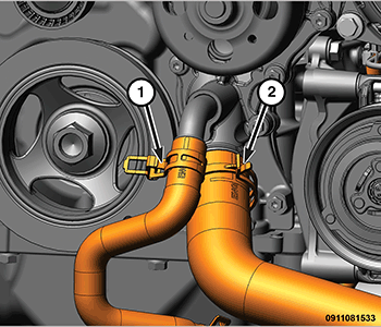
- Remove the lower radiator hose (2) from the water pump.
- Remove the heater core return hose (1) from the lower radiator coolant tube.
- Remove the front suspension crossmember. Refer to CROSSMEMBER, FRONT SUSPENSION, REMOVAL AND INSTALLATION .
- Remove both front axle shafts. Refer to REMOVAL AND INSTALLATION .
- Remove the Power Transfer Unit (PTU). Refer to REMOVAL AND INSTALLATION .
- Remove both catalytic converters. Refer to CONVERTER, CATALYTIC, REMOVAL AND INSTALLATION
.
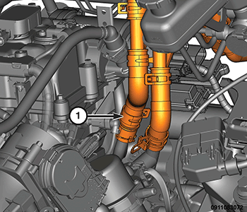
- Disconnect the A/C suction (1) and discharge (2) lines from the compressor and position aside.
- Disconnect the transmission oil cooler lines from the transaxle. Refer to TUBES AND HOSES, TRANSMISSION OIL COOLER, REMOVAL AND INSTALLATION
.
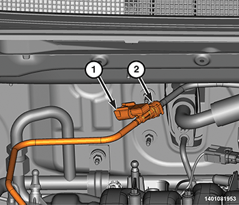
- Disconnect the wire harness connectors (2) from the power steering gear and disengage the harness from the retaining bracket (1).
- Disconnect and reposition the power cord from the engine block heater (if equipped).
- Remove the positive battery cable from the starter and alternator (1) and position aside.NOTE:
If the transaxle is to be eventually separated from the engine, removal of the torque converter bolts and lower transaxle mounting bolts are best accomplished at this time.
- If required, remove the transaxle torque converter housing dust cover (1).
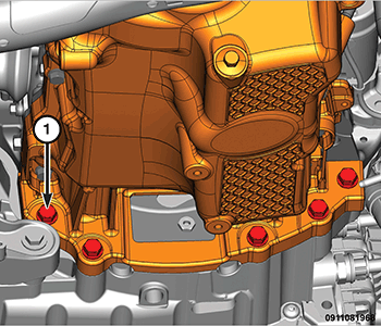
- If required, remove the torque converter-to-driveplate bolts.
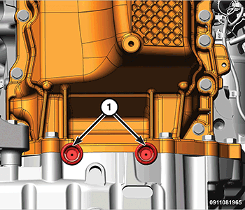
- Remove the two rubber plugs (1) covering the rear oil seal retainer flange bolts.
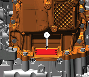
- If required, remove the five transaxle to oil pan bolts (1).
- Lower the vehicle.
- Remove the air cleaner body. Refer to BODY, AIR CLEANER, REMOVAL AND INSTALLATION .
- Remove the resonator. Refer to RESONATOR, AIR CLEANER, REMOVAL AND INSTALLATION .
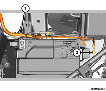
- Disconnect the ground wire from the left front wheelhouse panel (2).
- Disconnect the wire harness (1) connector from the relay control box and position harness to be removed with powertrain assembly.
- Disconnect the wire harness connector (1) from the powertrain control module.
- Disconnect the powertrain wire harness connector from the body harness connector (1) above the transmission and disengage from the transmission bracket (2).
- Disconnect the Manual Park Release (MPR) cable from the lever on the transmission (2) and the retaining bracket (1).
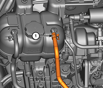
- Disconnect the heater core hoses (1).
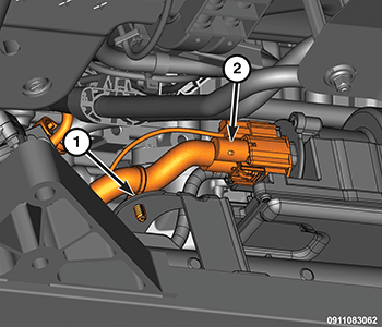
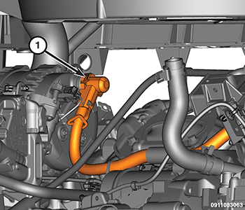
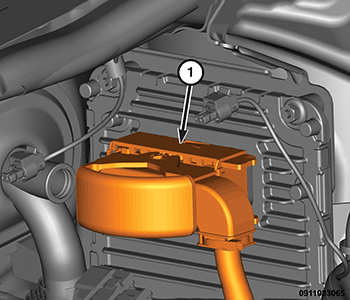
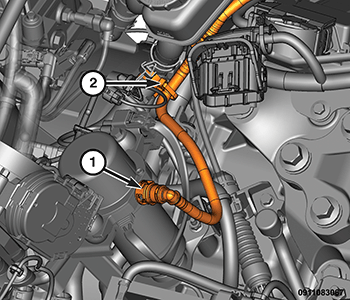
- Disconnect the brake vacuum hose from the electric vacuum pump (1) and retaining clip (2).
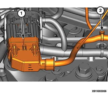
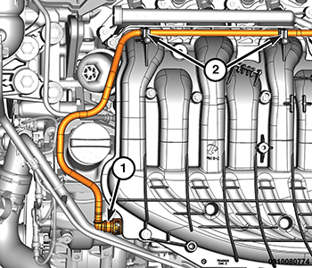
- Disconnect the brake vacuum hose from the upper intake manifold (1) and disengage the hose (2) from the intake manifold retaining clips.
- Disconnect the retaining clips (1) and position the brake vacuum hose (2) aside.
- Disconnect the fuel vapor hose (1).
- Disconnect the Fuel Rail Pressure Sensor (FRPS) wire harness connector (1).
- Disconnect the fuel supply line (2) at the FRPS. Refer to FUEL DELIVERY, GAS, STANDARD PROCEDURE
.
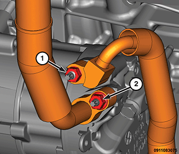
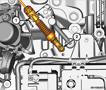
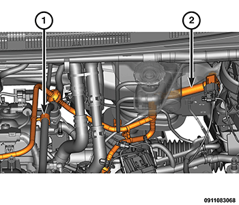
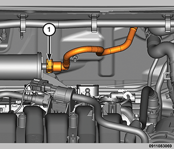
- Disconnect the Exhaust Gas Recirculation (EGR) cooler vent hose (1) from the pressurized coolant bottle.
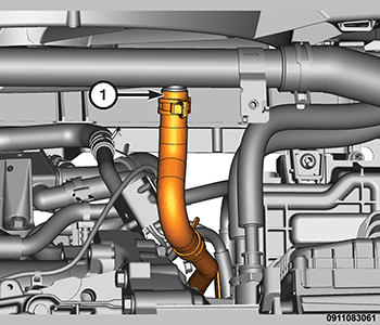
- Remove the upper radiator hose (1).
- Raise and position vehicle height to allow Power Train Dolly (special tool #6135, Dolly, Power Train) (3) and Engine Support Cradle (special tool #6710A, Cradle, Engine Support) (2) to be installed under the engine/transaxle assembly.
- Loosen the cradle engine mounts to allow movement for positioning onto the engine locating holes on the engine block and oil pan rail. Place Adapter (special tool #6848-3, Adapter) (1) on the front post and align to the oil pan mounting stud. Lower the vehicle and position cradle until the engine is resting on the posts. Tighten the post mounts to the cradle frame. Secure the engine/transaxle assembly to the dolly/cradle with safety straps (4).
- Lower the vehicle so that the weight of the engine and transmission ONLY is on the cradle.
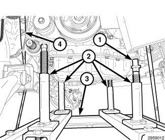
- Remove three bolts (1) from the LH engine (transmission) mount bracket.
- Remove the four bolts (1) from the RH engine mount bracket.
- Slowly raise the vehicle in short length spans. Inspect at each interval for potential engine or transaxle contact to vehicle components. Move the cradle/dolly fixture as necessary to allow for removal clearance.NOTE:
Perform the following steps to remove the transaxle from the engine if required.
- Position a transmission jack under the transaxle. Secure the transaxle to the transmission jack.
- Remove the electric vacuum pump and mounting bracket. Refer to PUMP, VACUUM, REMOVAL AND INSTALLATION .
- Remove the starter. Refer to STARTER, REMOVAL AND INSTALLATION .
- Remove the wiring harness from the transmission.
- Remove the remaining six transaxle to engine block bolts.
- Remove the transaxle and spacer plate from the engine.NOTE:
Perform the following steps to remove the engine from the cradle/dolly fixture if required.
- Remove the upper intake manifold. Refer to MANIFOLD, INTAKE, REMOVAL AND INSTALLATION .
- Remove the bolts and remove the upper intake manifold support brackets.
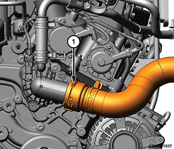
- Remove the exhaust gas recirculation cooler. Refer to COOLER, EXHAUST GAS RECIRCULATION (EGR), REMOVAL AND INSTALLATION .
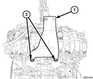
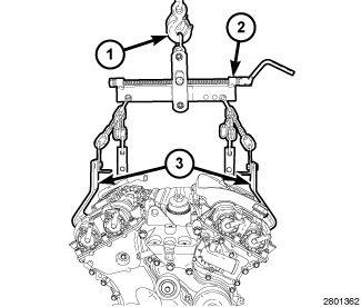
- Install the (special tool #2028020090, Lift Bracket, Engine-Left) (1) on the LH cylinder head with bolts (2) provided with the Engine Lifting Bracket. Tighten the bolts to the proper torque specification. Refer to TECHNICAL SPECIFICATIONS .
- Install the (special tool #2028010090, Lift Bracket, Engine-Right) (1) on the RH cylinder head with bolts (2) from the Engine Lifting Bracket. Tighten the bolts to the proper torque specification. Refer to TECHNICAL SPECIFICATIONS .
- Position a load-leveling lifting sling (2), such as OTC® 4305 Engine Load Leveler or equivalent, between the engine lifting brackets (3) and an engine hoist (1).
- Remove the engine from the cradle/dolly fixture.
- If required, remove the necessary components for installation onto the replacement engine.