Right Cylinder Head: Removal
- Perform the fuel pressure release procedure. Refer to FUEL DELIVERY, GAS, STANDARD PROCEDURE .
- Disconnect and isolate the negative battery cable.
- Remove the upper and lower intake manifolds and insulator. Refer to MANIFOLD, INTAKE, REMOVAL AND INSTALLATION .
- Raise and support the vehicle. Refer to HOISTING, STANDARD PROCEDURE .
- Drain the engine oil. Refer to OIL, STANDARD PROCEDURE .
- Remove the right side catalytic converter and position aside. Refer to CONVERTER, CATALYTIC, REMOVAL AND INSTALLATION
.
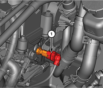
- Disconnect the oil temperature sensor wire harness connector (1).
- Disconnect the ignition coil capacitor electrical connector.
- Remove the spark plugs. Refer to SPARK PLUG, REMOVAL AND INSTALLATION .
- Remove the cylinder head covers and engine timing cover. Refer to COVER(S), ENGINE TIMING, REMOVAL AND INSTALLATION .NOTE:
Take this opportunity to measure timing chain wear. Refer to VALVE TIMING, STANDARD PROCEDURE .
CAUTION:When aligning timing marks, always rotate engine by turning the crankshaft. Failure to do so will result in valve or piston damage.
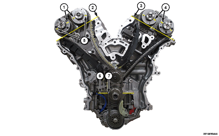
- Rotate the crankshaft clockwise to place the number one piston at Top Dead Center (TDC) on the exhaust stroke by aligning the dimple (7) on the crankshaft with the block/bearing cap junction (6). The left side cam phaser arrows (4) should point toward each other and be parallel to the valve cover sealing surface (3). The right side cam phaser arrows (5) should point away from each other and the scribe lines (1) should be parallel to the valve cover sealing surface (2).CAUTION:
Always reinstall timing chains so that they maintain the same direction of rotation. Inverting a previously run chain on a previously run sprocket will result in excessive wear to both the chain and sprocket.
- Mark the direction of rotation on the timing chain using a paint pen or equivalent to aid in reassembly.CAUTION:
When the timing chains are removed and the cylinder heads are still installed, DO NOT rotate the camshafts or crankshaft without first locating the proper crankshaft position. Failure to do so will result in valve or piston damage.
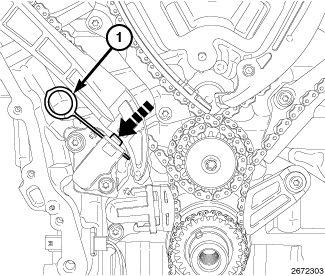
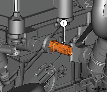
- Reset the RH cam chain tensioner by pushing back the tensioner piston and installing Tensioner Pin (special tool #8514A, Pins, Tensioner) (1).
- Remove the right camshafts. Refer to CAMSHAFT, ENGINE, REMOVAL AND INSTALLATION .NOTE:
If the rocker arms are to be reused, identify their positions so that they can be reassembled into their original locations.
- Remove the rocker arms. Refer to ROCKER ARM, VALVE, REMOVAL AND INSTALLATION .NOTE:
If the hydraulic lifters are to be reused, identify their positions so that they can be reassembled into their original locations.
- If required, remove the hydraulic lifters. Refer to LIFTER(S), HYDRAULIC, REMOVAL AND INSTALLATION .
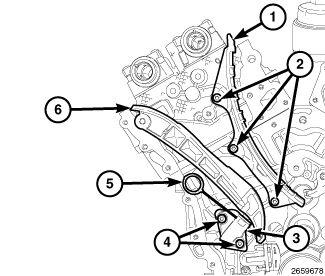
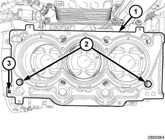
- Remove the RH cam chain tensioner arm (6).
- Remove the two bolts (4) and the RH cam chain tensioner (3).
- Remove the three bolts (2) and the RH cam chain guide (1).
CAUTION:
DO NOT use an impact gun or any type of power tools to break loose or remove the head bolts. This can cause the threads to pull out of the block with the bolts.
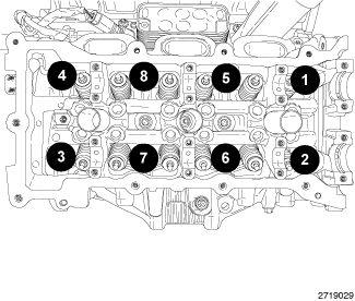
- Using the sequence shown in illustration, remove the cylinder head retaining bolts.WARNING:
The multi-layered steel head gaskets have very sharp edges that could cause personal injury if not handled carefully.
NOTE:The head gasket (1) crimps the locating dowels (2) and the dowels may pull out of the engine block when the head gasket is removed.
- Remove the cylinder head and gasket. Discard the gasket.CAUTION:
Do not lay the cylinder head on its gasket sealing surface, due to the design of the cylinder head gasket, any distortion to the cylinder head sealing surface may prevent the gasket from properly sealing resulting in leaks.
- If required, remove the oil temperature sensor (1) and the ignition coil capacitor.