Removal And Installation
REMOVAL
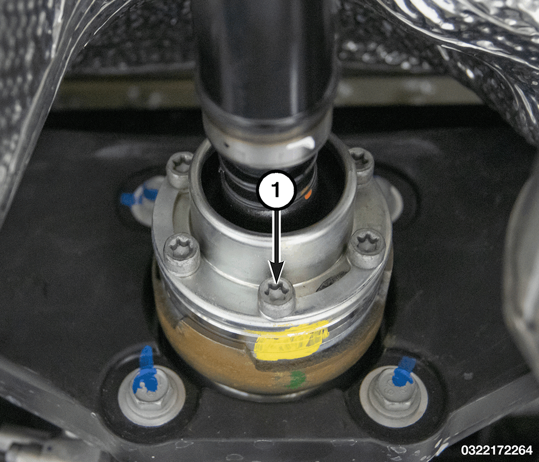
- Apply alignment index marks to the rear propeller shaft flange and the rear pinion flange.
- Remove and DISCARD the bolts (1) holding the rear propeller shaft flange to the rear pinion flange.
- Separate the rear propeller shaft from the rear pinion flange and secure the shaft to the side.
- Measure and record pinion turning torque.
- Using suitable chisel, remove the staking from the pinion nut.
- Remove the pinion nut.
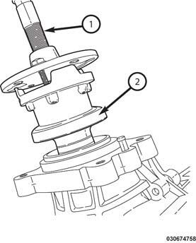
- Using the (special tool #C-452, Puller, Companion Flange) (1), remove the pinion flange (2).
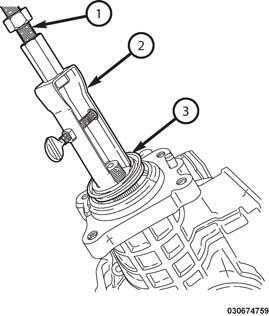
- Remove the pinion seal (3) using the (special tool #7794-A, Remover, Seal) (2) and (special tool #C-637, Slide Hammer, Universal) (1).
- Clean and inspect the sealing surface on the pinion flange, if damaged install a NEW pinion flange. If the pinion seal bore is damaged it will be necessary to replace the Rear Drive Unit (RDU) assembly.
INSTALLATION
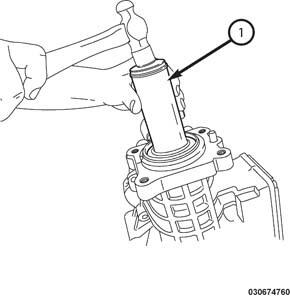
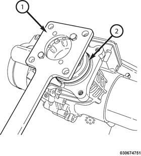
- Install the pinion seal using (special tool #9987, Installer, Seal) (1).
- Clean the pinion splines, apply Mopar® thread sealant meeting MS- CD95A or equivalent to the splines of the pinion flange.NOTE:
For pinion flange installation 3-5 in. lbs. must be added to the original measured pinion turning torque.
- Place the pinion flange on the splines of the pinion.
- Install a NEW
pinion nut and tighten using (special tool #8979, Wrench, Pinion Flange) (1).NOTE:
Do not over tighten pinion nut. The turning torque must be 3-5 in lbs. more than the turning torque before removal.
- Measure the pinion turning torque, adding 3-5 in. lbs. to pinion nut measurement that was measured before pinion flange removal.
- Using a suitable chisel, stake both sides of the pinion nut.
- Connect the rear propeller shaft and align the index marks on the rear propeller shaft flange and the rear pinion flange.NOTE:
The bolts that are used to secure the propeller shaft to the RDU input flange MUST be replaced. Do not reuse the bolts/washers.
NOTE:Use of Anti-seize compound is prohibited.
NOTE:Make sure the double washer is flat/flush to the joint housing prior to tightening the bolt to avoid damage to the washer, if damaged replace bolt washer assembly.
- Install NEW rear propeller shaft bolts (1) and tighten to the proper torque specifications. Refer to TECHNICAL SPECIFICATIONS .
- Fill the differential. Refer to FLUID, DIFFERENTIAL, STANDARD PROCEDURE .