Description And Operation: Description
An electrically-operated dual-note horn system is standard factory-installed equipment in this vehicle. The horn system features one low-note horn unit and one high-note horn unit. The horn circuit is protected by a 20 amp fuse located in the Power Distribution Center (PDC). The PDC also contains the horn relay. Pressing either side of the upper surface of the Driver Air Bag (DAB) trim cover in the center of the steering wheel actuates the horn switch contacts, which provides the vehicle operator with a convenient, audible signaling device that can be used to alert pedestrians or the operators of other vehicles in near proximity.
The horn system includes the following major components, which are described in more detail elsewhere in this service information:
- Horn Relay - The horn relay is an International Standards Organization (ISO) micro relay located within the PDC. The PDC is located on the left side of the engine compartment outboard of and behind the battery.
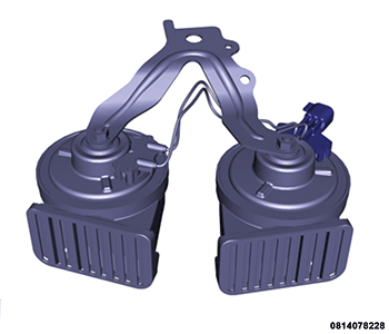
- Horns - The low note and high note electromagnetic diaphragm-type trumpet horns are secured by a single mounting bracket to the right outboard end of the front end module, just below the closeout panel between the top of the radiator and front fascia.
- Horn Switch Plate - The floating horn switch plate is secured to the back of the DAB housing within the steering wheel hub cavity and also serves as the mounting bracket between the DAB and the steering wheel. The horn switch rotates with the steering wheel and is connected to the vehicle electrical system through a pass-through circuit of the Steering Column Control Module (SCCM) at the top of the steering column.
- Power Distribution Center - The PDC is located on the left side of the engine compartment outboard of and behind the battery.
Hardwired circuitry connects the various horn system components to each other through the electrical system of the vehicle. These hardwired circuits are integral to several wire harnesses, which are routed throughout the vehicle and retained by many different methods. These circuits may be connected to each other and to the vehicle electrical system through the use of a combination of soldered splices, splice block connectors and many different types of wire harness terminal connectors and insulators. Refer to the appropriate wiring information. The wiring information includes wiring diagrams, details of wire harness routing and retention, connector pin-out information and location views for the various wire harness connectors, splices and grounds. For proper wire repair, and connector repair procedures. Refer to STANDARD PROCEDURE , REMOVAL and INSTALLATION .