Diagnostic Test
- CHECK FOR ANY SERVICE BULLETINS OR PCM SOFTWARE UPDATES
- Check for any applicable Service Bulletins or Flash updates related to the DTC.
Are there any applicable Service Bulletins or Flash updates?
Yes
- Perform the applicable repair.
- Perform the POWERTRAIN VERIFICATION TEST. Refer to POWERTRAIN VERIFICATION TEST .
No
- Go To 2
- Check for any applicable Service Bulletins or Flash updates related to the DTC.
- CHECK FOR OTHER DTCS
- With the scan tool, read DTCs in all Electronic Control Units (ECUs) and record on the repair order.
- For future reference, with the scan tool, run and save a vehicle Scan Report and all related recorded data.
Are there any Power Control Relay, PCR Control Relay or charging system DTCs present?
Yes
- Perform the applicable diagnostic procedure(s). Refer to DTC TROUBLESHOOTING .
No
- Go To 3
- CHECK THE FUSES AND PDC CONNECTIONS
- Check the Fuse(s) that feed the PCM Fused B+ circuit.
- Check the Auxiliary Battery cable connection at the PDC for a proper connection.
Were any issues found with the fuses or connections?
Yes
- Make the necessary repairs.
- Perform the POWERTRAIN VERIFICATION TEST. Refer to POWERTRAIN VERIFICATION TEST .
No
- Go To 4
- CHECK THE PCR CONTROL RELAY (T760) OUTPUT CIRCUIT VOLTAGE
- Turn the ignition off.
- Disconnect the Power Control Relay C1 harness connector.
- Using a 12 volt test light connected to ground, back probe PCR Control Relay (T762) Control circuit to energize the relay.
- Turn the ignition on.
- Measure the voltage on the PCR Control Relay (T762) Control circuit at the Power Control Relay C1 harness connector.
Is Battery voltage present on the PCR Control Relay (T760) Output circuit?
Yes
- Go To 7
No
- Go To 5
- CHECK THE PCR CONTROL RELAY (T760) OUTPUT CIRCUIT FOR A SHORT TO GROUND
- Turn the ignition off.
- Disconnect the PDC C3 harness connector.
- Check for continuity between ground and the PCR Control Relay (T760) Output circuit at the Power Control Relay harness connector.
Is there continuity between ground and the PCR Control Relay (T760) Output circuit?
Yes
- Repair the PCR Control Relay (T760) Output circuit for a short to ground and check the fuses in the PDC.
- Perform the POWERTRAIN VERIFICATION TEST. Refer to POWERTRAIN VERIFICATION TEST .
No
- Go To 6
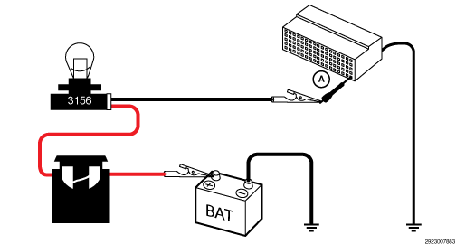
- ISOLATE AND LOAD TEST THE PCR CONTROL RELAY (T760) OUTPUT CIRCUIT TO CHECK FOR HIGH RESISTANCE NOTE:
Read the CIRCUIT LOAD TESTING PROCEDURE for information on building a simple load test tool and for additional load testing information and alternative methods of load testing or voltage drop testing a circuit. Refer to CIRCUIT LOAD TESTING PROCEDURES .
CAUTION:Do not load test any circuits with components still connected to the circuit.
- Disconnect the PDC harness connector.
- Connect the (special tool #10436, Adapter, GPEC Diagnostic) to the appropriate PCM connector.NOTE:
IMPORTANT - The GPEC Diagnostic Adaptor can add up to 1.5 Ohms of resistance to the circuit.
- Load test the PCR Control Relay (T760) Output circuit. Note:
refer to the example illustration.NOTE:
The bulb on the load test tool should be illuminated and bright if there is no resistance in the circuit. Compare the brightness of the bulb in the load test tool to that of a direct connection across Battery.
Is the load test bulb illuminated and bright?
Yes
- If there were no open fuses in the PDC, replace the PDC in accordance with the Service Information.
- Perform the POWERTRAIN VERIFICATION TEST. Refer to POWERTRAIN VERIFICATION TEST .
No
- Repair the PCR Control Relay (T760) Output circuit for an open or high resistance.
- Perform the POWERTRAIN VERIFICATION TEST. Refer to POWERTRAIN VERIFICATION TEST .
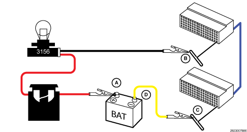
- CHECK THE (Z917) GROUND CIRCUIT FOR HIGH RESISTANCE BY LOAD TESTING THE CIRCUIT NOTE:
Read the CIRCUIT LOAD TESTING PROCEDURE for information on building a simple load test tool and for additional load testing information and alternative methods of load testing or voltage drop testing a circuit. Refer to CIRCUIT LOAD TESTING PROCEDURES .
CAUTION:Do not load test any circuits with components still connected to the circuit.
- Turn the ignition off.
- Load test the (Z917) Ground circuit at the Power Control Relay harness connector (A). Note:
refer to the diagram below.NOTE:
The bulb on the load test tool should be illuminated and bright if there is no resistance in the circuitry. Compare the brightness of the bulb in the load test tool to that of a direct connection across Battery.
Is the load test bulb illuminated and bright?
Yes
- Go To 8
No
- Repair the (Z917) Ground circuit for an open or high resistance.
- Perform the POWERTRAIN VERIFICATION TEST. Refer to POWERTRAIN VERIFICATION TEST .
- CHECK THE POWER CONTROL RELAY FOR PROPER OPERATION
- Reconnect the Power Control Relay C1 harness connector.NOTE:
The Power Control Relay can be checked in one of two ways.
- Method 1: Remove the eyelet from the Power Control Relay C2 post. Leave the C3 eyelet connected to the Power Control Relay. The C2 eyelet is still connected to Main Cranking Battery. Be careful to insulate and/or isolate the cable so that it cannot make contact with any engine ground.
- Using a 12 volt test light connected to ground, back probe PCR Control Relay (T762) Control circuit to energize the relay and measure the voltage at the C2 post of the Power Control Relay with the C2 eyelet removed and the C3 eyelet still connected.NOTE:
The Power Control Relay should be open when energized and there should be no voltage at the C2 post.
- Method 2:
Start the engine to allow the charging system to become active. Using a 12 volt test light connected to ground, back probe PCR Control Relay (T762) Control circuit to energize the relay and measure the voltage at both of the Power Control Relay posts.NOTE:
The Power Control Relay should be open when energized and the voltage on the C2 post should be equal to the Auxiliary Battery voltage and not charging system output voltage.
Is the Power Control Relay functioning properly?
Yes
- Go To 9
No
- Replace the Power Control Relay in accordance with the Service Information.
- Perform the POWERTRAIN VERIFICATION TEST. Refer to POWERTRAIN VERIFICATION TEST .
- Reconnect the Power Control Relay C1 harness connector.
- CHECK THE AUXILIARY BATTERY POSITIVE AND NEGATIVE CABLE CONNECTIONS NOTE:
A faulty Auxiliary Battery or high resistance in the cables could cause the voltage on the Auxiliary side of the system to drop low enough that it could appear as though the connection is not being broken between the Batteries when the Power Control Relay is energized during an auto start event.
- Check for a proper connection between the Battery posts and cable ends at the Auxiliary Battery.NOTE:
There should be no voltage drop between the posts and cable ends.
Is there a good connector between the posts and cable ends?
Yes
- Go To 10
No
- Clean the Battery Cables and posts and retest.
- Perform the POWERTRAIN VERIFICATION TEST. Refer to POWERTRAIN VERIFICATION TEST .
- Check for a proper connection between the Battery posts and cable ends at the Auxiliary Battery.
- CHECK FOR HIGH RESISTANCE IN THE AUXILIARY BATTERY CABLE
- Perform a voltage drop on the Auxiliary Battery Positive cable between the Auxiliary Battery Positive Cable End and the Power Control Relay.
- Perform a voltage drop on the Auxiliary Battery Positive cable between the Auxiliary Battery Positive Cable End and the connection at the PDC.
Does the Auxiliary Battery Positive Cable have a voltage drop between the Auxiliary Battery and Power Control Relay or PDC?
Yes
- Repair or replace the Auxiliary Battery Positive Cable.
- Perform the POWERTRAIN VERIFICATION TEST. Refer to POWERTRAIN VERIFICATION TEST .
No
- Go To 11
- CHECK AUXILIARY BATTERY NEGATIVE CABLE AND GROUND LOCATION
- Check the Auxiliary Battery Negative Cable for a proper ground.
Is the Negative Battery Cable grounded properly?
Yes
- Go To 12
No
- Repair or replace the Auxiliary Battery Negative Cable or ground.
- Perform the POWERTRAIN VERIFICATION TEST. Refer to POWERTRAIN VERIFICATION TEST .
- Check the Auxiliary Battery Negative Cable for a proper ground.
- CHECK THE AUXILIARY BATTERY STATE OF CHARGE
- Turn the ignition off.
- Disconnect the Negative Cable from both Batteries.
- Use the (special tool #GR8-1220KIT-CHRY, AGM Battery Tester/Charger Station) or equivalent to load test the Battery.
Did the Auxiliary Battery pass the load test?
Yes
- Go To 13
No
- Recharge or replace the Auxiliary Battery and retest.
- Perform the POWERTRAIN VERIFICATION TEST. Refer to POWERTRAIN VERIFICATION TEST .
- CHECK (A209) FUSED B+ SUPPLY VOLTAGE TO THE PCM
- Disconnect the PCM C1 harness connector.
- Connect the(special tool #10436, Adapter, GPEC Diagnostic) to the PCM harness connector. Reconnect the PCM C1 harness connector in-line with the GPEC Adaptor connected in-line.
- Turn the ignition on.
- Measure the voltage on the (A209) Fused B+ circuit at the GPEC Adaptor.
- Measure the voltage of the Auxiliary Battery.
Is the voltage on the (A209) Fused B+ circuit within 0.2 volts of the Auxiliary Battery?
Yes
- Go To 14
No
- Repair the (A209) Fused B+ circuit for high resistance.
- Perform the POWERTRAIN VERIFICATION TEST. Refer to POWERTRAIN VERIFICATION TEST .
- CHECK RELATED PCM AND COMPONENT CONNECTIONS
- Perform any Service Bulletins that apply.
- Disconnect all PCM harness connectors.
- Disconnect all related in-line harness connections (if equipped).
- Disconnect the related component harness connectors.
- Inspect harness connectors, component connectors, and all male and female terminals for the following conditions:
- Proper connector installation.
- Damaged connector locks.
- Corrosion.
- Other signs of water intrusion.
- Weather seal damage (if equipped).
- Bent terminals.
- Overheating due to a poor connection (terminal may be discolored due to excessive current draw).
- Terminals that have been pushed back into the connector cavity.
- Check for spread terminals and verify proper terminal tension.
Repair any conditions that are found.
- Reconnect all PCM harness connectors. Be certain that all harness connectors are fully seated and the connector locks are fully engaged.
- Reconnect all in-line harness connectors (if equipped). Be certain that all connectors are fully seated and the connector locks are fully engaged.
- Reconnect all related component harness connectors. Be certain that all connectors are fully seated and the connector locks are fully engaged.
- With the scan tool, erase DTCs.
- Test drive or operate the vehicle in accordance with the when monitored and set conditions.
- With the scan tool, read DTCs.
Did the DTC return?
Yes
- Replace and program the Powertrain Control Module (PCM) in accordance with the Service Information. Refer to MODULE, POWERTRAIN CONTROL (PCM), REMOVAL AND INSTALLATION .
- Perform the POWERTRAIN VERIFICATION TEST. Refer to POWERTRAIN VERIFICATION TEST .
No
- The wiring or poor connection problem has been repaired.
- Perform the POWERTRAIN VERIFICATION TEST. Refer to POWERTRAIN VERIFICATION TEST .