Diagnostic Test
- CHECK FOR ANY SERVICE BULLETINS OR SOFTWARE UPDATES
- Check for any applicable Service Bulletins or Flash updates related to the DTC.
Are there any applicable Service Bulletins or Flash updates?
Yes
- Perform the applicable repair.
- Perform the BODY VERIFICATION TEST. Refer to BODY VERIFICATION TEST .
No
- Go To 2
- Check for any applicable Service Bulletins or Flash updates related to the DTC.
- READ AND RECORD DTCS AND ENVIRONMENTAL DATA - ERASE DTCS AND CHECK FOR THE DTC TO RETURN
- With the scan tool, read DTCs in all Electronic Control Units (ECUs) and record on the repair order.
- For future reference, run and save a vehicle Scan Report and all related recorded data.
- With the scan tool, erase all DTCs.
- Turn the ignition off for a minimum of 10.0 seconds.
- Turn the ignition on.
- Using the When Monitored and Set Conditions above and recorded data, operate the vehicle in the conditions that set the DTC.
- With the scan tool, read DTCs.
Did the DTC return?
Yes
- Go To 3
No
- Perform the TESTING FOR AN INTERMITTENT CONDITION procedure. Refer to TESTING FOR AN INTERMITTENT CONDITION .
- CHECK FOR OTHER DTCS
- CHECK THE FUSED IGNITION (F948) RUN/START CIRCUIT FOR HIGH RESISTANCE BY LOAD TESTING THE CIRCUIT NOTE:
Read the CIRCUIT LOAD TESTING PROCEDURE for information on building a simple load test tool and for additional load testing information and alternative methods of load testing or voltage drop testing a circuit. Refer to CIRCUIT LOAD TESTING PROCEDURES .
- Turn the ignition off.
- Disconnect the Park Assist Module (PAM) C1 harness connector.CAUTION:
Do not load test any circuits with components still connected to the circuit.
- Turn the ignition on.
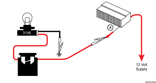
- Load test the Fused Ignition (F948) Run/Start circuit at the PAM C1 harness connector. Note:
refer to the example illustration.NOTE:
The bulb on the load test tool should be illuminated and bright if there is no resistance in the circuitry. Compare the brightness of the bulb in the load test tool to that of a direct connection across Battery.
Is the load test bulb illuminated and bright?
Yes
- Go To 5
No
- Repair the Fused Ignition (F948) Run/Start circuit for an open or high resistance. If the fuse is found to be open, check the circuit for a short to ground.
- Perform the BODY VERIFICATION TEST. Refer to BODY VERIFICATION TEST .
- CHECK THE (Z922) GROUND CIRCUIT FOR HIGH RESISTANCE BY LOAD TESTING THE CIRCUIT NOTE:
Read the CIRCUIT LOAD TESTING PROCEDURE for information on building a simple load test tool and for additional load testing information and alternative methods of load testing or voltage drop testing a circuit. Refer to CIRCUIT LOAD TESTING PROCEDURES .
- Turn the ignition off.CAUTION:
Do not load test any circuits with components still connected to the circuit.
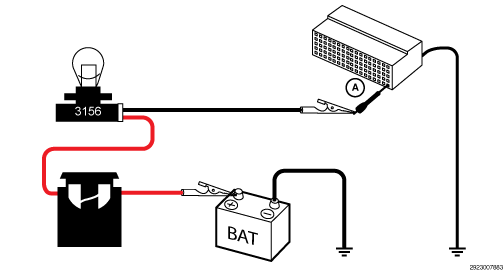
- Load test the (Z922) Ground circuit at the PAM C1 harness connector (A). Note:
refer to the diagram below.NOTE:
The bulb on the load test tool should be illuminated and bright if there is no resistance in the circuitry. Compare the brightness of the bulb in the load test tool to that of a direct connection across Battery.
Is the load test bulb illuminated and bright?
Yes
- Go To 6
No
- Repair the (Z922) Ground circuit for an open or high resistance.
- Perform the BODY VERIFICATION TEST. Refer to BODY VERIFICATION TEST .
- Turn the ignition off.
- CHECK RELATED PAM HARNESS CONNECTIONS
- Disconnect all PAM harness connectors.
- Disconnect all related in-line harness connections (if equipped).
- Disconnect the related component harness connectors.
- Inspect harness connectors, component connectors, and all male and female terminals for the following conditions:
- Proper connector installation.
- Damaged connector locks.
- Corrosion.
- Other signs of water intrusion.
- Weather seal damage (if equipped).
- Bent terminals.
- Overheating due to a poor connection (terminal may be discolored due to excessive current draw).
- Terminals that have been pushed back into the connector cavity.
- Perform a terminal drag test on each connector terminal to verify proper terminal tension.
Repair any conditions that are found.
- Reconnect all PAM harness connectors. Be certain that all harness connectors are fully seated and the connector locks are fully engaged.
- Reconnect all in-line harness connectors (if equipped). Be certain that all connectors are fully seated and the connector locks are fully engaged.
- Reconnect all related component harness connectors. Be certain that all connectors are fully seated and the connector locks are fully engaged.
- With the scan tool, erase DTCs.
- Using the recorded Environmental Data, along with the When Monitored and Set Conditions above, operate the vehicle in the conditions that set the DTC.
- With the scan tool, read DTCs.
Did the DTC return?
Yes
- Replace the Park Assist Module (PAM) in accordance with the Service information. Refer to MODULE, PARK ASSIST, REMOVAL AND INSTALLATION .
- Perform the BODY VERIFICATION TEST. Refer to BODY VERIFICATION TEST .
No
- The wiring or poor connection has been repaired
- Perform the BODY VERIFICATION TEST. Refer to BODY VERIFICATION TEST .