Description And Operation: Description
The 948TE/9HP48 9-speed automatic transmission with electronic shift control has an integrated Transmission Control Module (TCM) mounted to the transmission case. All functions are completely electronic.
The 948TE/9HP48 9-speed automatic transmission includes the following features:
- nine forward speeds.
- lock-up torque converter.
- filled-for-life transmission fluid, no dipstick required.
- electronic rotary shifter located in the center console.
- park lock mechanism with manual park release.
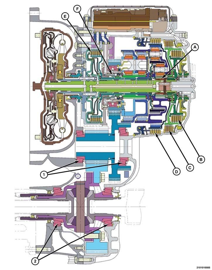
| A | A Clutch Dog Clutch |
| B | B Clutch |
| C | C Clutch |
| D | D Clutch |
| E | E Clutch |
| F | F Clutch Dog Clutch |
| 1 | Transfer Gear Bearings |
| 2 | Differential Bearings |
Torque Converter
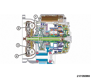
The torque converter includes:
- unique housing shape to incorporate multi-disc (2) Torque Converter Clutch (TCC).
- a multi-disc torque converter clutch system improves durability and the holding pressure in the lock-up circuit.
- a TCC which can engage in any of the nine forward gears.
- a turbine dampening system (1) suppresses torsional vibrations from the engine to ensure optimal shift quality and reduce Noise, Vibration, And Harshness (NVH) concerns.
The torque converter is attached to the engine drive plate with three sets of two bolts.
Transmission Fluid Pump
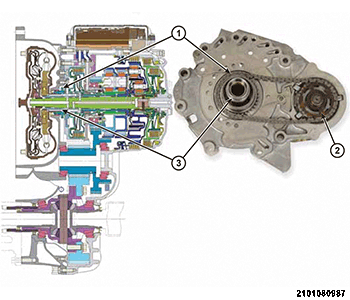
The transmission fluid pump:
- is located in the transmission fluid pump housing inside the bell housing of the transmission case.
- consists of an inner and outer gear, a housing, and a cover that also serves as the reaction shaft support.
- is driven by the torque converter using a chain and sprockets.
- is a double-stroke vane pump.
- has dual chambers with two inlet and two outlet ports which assists with fluid volume.
- filter is mounted directly to the transmission fluid pump and is not serviced through the transmission fluid pan. It is only replaced as part of a major transmission repair.
Differential and Ring Gear
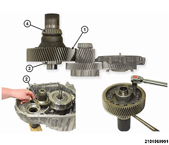
The differential and ring gear assembly consists of:
- a ring gear (1).
- a preload shim (2).
- a case side support bearing (3).
- a bellhousing side support bearing (4).
The ring gear (1) is bolted to the differential housing. Opposing tapered roller bearings (3, 4) support the housing. A shim (2) located under the case side bearing race provides bearing preload adjustment.
Transmission Fluid Pressure Sensor
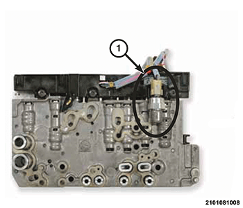
The transmission fluid pressure sensor (1) is located in the valve body.
The transmission fluid pressure sensor output is monitored by the TCM for control and diagnostics. The TCM can use the pressure value provided by the transmission fluid pressure sensor to compute the system pressure and clutch apply pressure using a proprietary software algorithm.
Transmission Fluid Temperature Sensor
The transmission fluid temperature sensor (1) is part of the transmission pass-through wiring harness. The TCM uses the sensor to monitor transmission oil temperature.
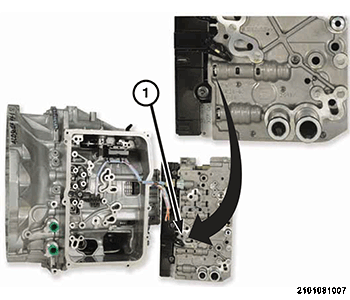
Speed Sensors
The input and output speed sensors (1) are part of a single assembly located under the valve body. The speed sensors are active digital sensors.
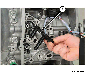
Transmission Range Sensor (TRS)
The Transmission Range Sensor (TRS) (1) is a non-contact Hall-effect sensor. It is a three wire sensor and has two signals: park and not-in-park.
Transmission E-Shifter
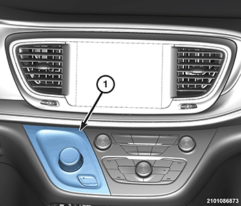
Gear range selection on the 948TE/9HP48 transmission is accomplished using an electronic shifter (1). The e-shifter has an integrated Gear Shift Module (GSM) with position sensing/neutral block release. The e-shifter communicates on Controller Area Network-C (CAN-C) bus as well as having dedicated CAN bus communication with the Transmission Control Module (TCM) to control gear shift selection instead of a conventional cable. With the ignition on and the brake pedal applied, the driver can rotate the shift knob to select either PARK, REVERSE, NEUTRAL, or DRIVE positions. The driver request is transmitted over CAN-C to the TCM.
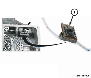
Electronic Shifter Module (ESM)
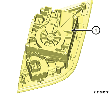
The Electronic Shift Module (ESM) (1) is part of the transmission e-shifter assembly and monitors gear selection. The ESM communicates on the CAN-C. The ESM provides the park signal to the Radio Frequency Hub Module (RFHM).
Manual Park Release (MPR) Lever
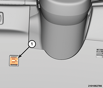
The vehicle is equipped with a Manual Park Release (MPR) Lever. This allows the vehicle to be taken out of PARK in the event there is a loss of vehicle electrical power.
The MPR will allow first responders to disengage the parking pawl and allow the vehicle to be moved, assisting with vehicle recovery such as towing or moving the vehicle to allow jump starting. The MPR cable is attached to a bracket on top of the transmission and actuates the park mechanism lever. The other end of the cable is attached to a release lever and pull loop (1) located at the left side of the instrument panel.
Valve Body
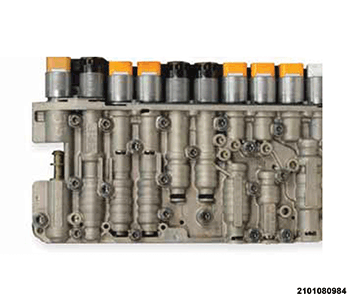
The valve body assembly contains all the sensors and solenoids which the TCM strategy requires for operation inside the transmission.
The solenoids contained in the valve body are:
- Mechanical Park-Lock Solenoid
- Park Control Solenoid
- C Clutch Solenoid
- D Clutch Solenoid
- F Dog Clutch Solenoid
- A Dog Clutch Solenoid
- E Clutch Solenoid
- B Clutch Solenoid
- TCC Solenoid
- System (line) Pressure Solenoid
Transmission Control Module (TCM)
The Transmission Control Module (TCM) is mounted on the outside of the transmission case, over the differential.
The electronic control system consists of various components providing inputs to the TCM.
- The TCM monitors transmission sensors, shifter assembly, and bus messages to determine transmission shift strategy.
- After shift strategies are determined, the TCM controls the actuation of transmission solenoids, which controls the routing of hydraulic fluid within the transmission, by moving a sequence of four valves to make a shift occur.
- The system performs its functions based on continuous real-time sensor feedback information.
- The TCM activates the solenoid valves and moves valves in the valve body to achieve the necessary gear changes.
The TCM receives information from the rest of the vehicle over the CAN C bus.
- The CAN C bus is a high-speed communication bus that allows real time control capability between various controllers.
- Most messages are sent every 20 milliseconds.
- This means critical information can be shared between the transmission, engine, and ABS controllers.
- The CAN C bus is a two wire bus with a CAN C Bus (+) circuit and a CAN C Bus (-) circuit.
- These circuits are twisted pairs in the harness to reduce the potential of radio and noise interference.
- The transmission control system automatically adapts to changes in engine performance, vehicle speed, and transmission temperature variations to provide consistent shift quality.
- The control system ensures that clutch operation during up-shifting and downshifting is more responsive without increased harshness.
- The required pressure level is calculated from the load condition, engine speed.
- Vehicle speed (from Anti-lock Brake System (ABS) module) and transmission oil temperature, matched to the torque to be transmitted.
- Power for the transmission system is supplied through the shifter mechanism (no transmission control relay).