Description And Operation: Operation
The 948TE transmission includes:
- a wide 9.79 ratio spread for enhanced performance and fuel economy.
- a compact design for ease of packaging.
- high efficiency in all gears and speeds thanks to nested carriers, dog clutches, and advanced hydraulic control unit architecture.
The 948TE's wide ratio spread brings outstanding launch characteristics, smooth, indecipherable transfer between gears, and fuel efficiency.
The launch ratios:
- Starting with a first gear of 4.70 - ensure quick take-off qualities that have been tuned to the vehicles' structure, size and weight.
- A host of shorter, mid-range gears ensures short transitions between gears for smooth, virtually unnoticeable conversions.
- The shorter steps between gears translates to extremely manageable "bump and shudder-free" transitions and enhanced noise/vibration characteristics.
- Higher gears - in the seventh, eighth, and ninth transitions, relate to lower engine speeds, and enhanced fuel efficiency on the order of 10 to 16%.
- In all, the wider gear ratio spread on the 948TE is unmatched in the industry from launch to overdrive.
The transmission name indicates key characteristics:
- The numeral "9" indicates that the transmission has nine forward gear speeds.
- The numeral "48" indicates the transmission torque capacity of 480 Newton meters.
- The "T" indicates that the transmission is transverse-mounted.
- The "E" indicates that the transmission is electronically controlled.
| Gear | Ratios |
| 1 | 4.70:1 |
| 2 | 2.84:1 |
| 3 | 1.91:1 |
| 4 | 1.38:1 |
| 5 | 1.00:1 |
| 6 | 0.81:1 |
| 7 | 0.70:1 |
| 8 | 0.58:1 |
| 9 | 0.48:1 |
| Reverse | 3.81:1 |
| Spread | 9.79:1 |
| Final Drive * | 3.73:1 |
| Maximum Shift Speed | 6500 rpm |
| Torque Converter | 242 mm (9.531 in.) |
| SHIFT SOLENOID | CLUTCH-A | CLUTCH-B | CLUTCH-C | CLUTCH-D | CLUTCH-E | CLUTCH-F | RATIO | |
|---|---|---|---|---|---|---|---|---|
| GEAR | 1st | X | X | X | 4.700 | |||
| GEAR | 2nd | X | X | X | 2.842 | |||
| GEAR | 3rd | X | X | X | 1.909 | |||
| GEAR | 4th | X | X | X | 1.382 | |||
| GEAR | 5th | X | X | X | 1.000 | |||
| GEAR | 6th | X | X | X | 0.808 | |||
| GEAR | 7th | X | X | X | 0.699 | |||
| GEAR | 8th | X | X | X | 0.580 | |||
| GEAR | 9th | X | X | X | 0.479 | |||
| GEAR | NEUTRAL/PARK | X | X | |||||
| GEAR | REVERSE | X | X | X | 3.805 | |||
| DEFAULT GEAR | 4th | X | X | |||||
Torque Converter
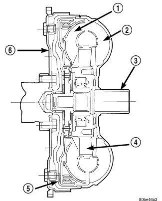
The torque converter:
- is a hydraulic device that couples the engine crankshaft to the transmission.
- consists of an outer shell with an internal turbine (1), a stator (4), an over-running clutch, an impeller (2) and an electronically applied converter clutch (5).
- clutch provides reduced engine speed and greater fuel economy when engaged.
- hub (3) drives the transmission fluid pump.
- is a sealed, welded unit that is not repairable and is serviced as an assembly.
Transmission Fluid Pump
The transmission fluid pump:
- is located in the transmission fluid pump housing inside the bell housing of the transmission case.
- consists of an inner and outer gear, a housing, and a cover that also serves as the reaction shaft support.
- is driven by the torque converter using a chain and sprockets.
- is a double-stroke vane pump.
- has dual chambers with two inlet and two outlet ports which assists with fluid volume.
- filter is mounted directly to the transmission fluid pump and is not serviced through the transmission fluid pan. It is only replaced as part of a major transmission repair.
As the torque converter rotates, the converter hub rotates the inner and outer gears. As the gears rotate, the clearance between the gear teeth increases in the crescent area, and creates a suction at the inlet side of the pump. This suction draws fluid through the pump inlet from the oil pan. As the clearance between the gear teeth in the crescent area decreases, it forces pressurized fluid into the pump outlet and to the valve body.
Differential and Ring Gear
The ring gear is bolted to the differential housing. The final drive pinion transmits power to the ring gear. Opposing tapered roller bearings support the housing. A shim located under the case side bearing race provides bearing preload adjustment.
The final drive of the transmission includes three gear assemblies: the output gear assembly, the transfer gear assembly, and the differential/ring gear assembly. The P4 carrier transmits power to the output gear through splines on the face of the output gear. The output gear is attached to the output gear support with a spanner nut. Power from the output gear is transmitted to the transfer gear assembly via the driven transfer gear.
Manual Park Release (MPR) Lever
The system includes Manual Park Release (MPR) feature for Shifter/Transmission Override to provide the ability to disengage Park.
Transmission Fluid Pressure Sensor
The transmission fluid pressure sensor is mounted to the valve body and monitors the dog clutch hydraulic exhaust circuit. The sensor reacts to the pressure changes that occur during dog clutch engagement and disengagement.
Transmission Fluid Temperature Sensor
The transmission temperature sensor is part of the transmission pass-through wiring harness. The TCM uses the sensor to monitor transmission oil temperature.
Speed Sensors
The input and output speed sensors are part of a single assembly located under the valve body. The speed sensors are active digital sensors. The input speed sensor uses the E clutch housing as a reluctor, and the output speed sensor uses the transfer gear.
Transmission Range Sensor (TRS)
The Transmission Range Sensor (TRS) is a park-by-wire and non-contact Hall-effect sensor with multiple signal outputs. It is a three-wire sensor and produces only two signals (values); park and not-in-park.
Transmission Shifter
- The transmission uses a shift-by-wire system, so there is no mechanical connection between the shifter and the transmission.
- The TCM allows unlocking of rotary knob as well as engagement of non-Park positions based on brake input and BTSI conditions.
- The park linkage inside the transmission is spring-loaded to default into the park position.
- The parking pawl engages into the teeth of the parking gear on the carrier to prevent movement.
- The TCM acquires information on the shifter knob position from the ESM
Valve Body
Valve body function is directed by the TCM. There is a solenoid for each of the six clutches, plus one for TCC and one for system pressure. There are two solenoids used by the park-by-wire system: a hydraulic apply solenoid (called the park control solenoid) and a mechanical solenoid to operate the parking pawl (called the park-lock solenoid). There are no mechanical connections between the shifter and the transmission. The park control solenoid routes pressure to the park-lock valve. The valve is attached to the linkage that moves the parking pawl out of the park position. A mechanical park-lock solenoid latches onto the end of the parking-lock valve to hold the valve out of the park position. The valve is spring-loaded to default into the park position when power is removed from the park-lock solenoid. However, the hydraulic park valve will not move to the park position until the park control solenoid is de-energized. When the transmission is placed in park, the TCM commands the park control solenoid to release the hydraulic pressure holding the parking pawl away from the park gear, and the park-lock solenoid releases the mechanical hold on the park-lock valve. If a fault occurs while the transmission is out of park, the TCM may de-energize all solenoids. At this point, the F dog hydraulic release circuit will hold the parking lock valve out of park until the engine is stopped. Moving the electronic park-by-wire shifter to the park position will not engage the parking pawl during certain faults.
Transmission Control Module (TCM)
The Transmission Control Module (TCM) regulates the amount of hydraulic pressure used to engage the clutches and the Torque Converter Clutch (TCC), in addition to directing hydraulic pressure to engage or release any given clutch for any given required gear.
The TCM will actuate the valves via solenoids based on the position of the shifter, transmission fluid temperature, engine operating conditions, traction conditions and driver demands.
During a shift, the TCM will actuate the solenoids to match the gear ranges to the optimal torque range of the engine based on the position of the accelerator pedal, shifter and vehicle speed as determined by the PCM based on input from the Vehicle Speed Sensor (VSS) and Anti-lock Brake System (ABS) module.
Due to the complexity of the 948TE transmission control system, always when attempting to diagnose transmission problems. Refer to DIAGNOSTIC CODE INDEX .
Some examples of
direct inputs
to the TCM are:
- Battery (B+) voltage
- Ignition Status
- Transmission Range Sensor (TRS)
- Cruise Control Switch
- Throttle Position
- Body Control Module (BCM)
- Shifter Position
- Pressure Switches
- Transmission Temperature Sensor
- Input Shaft Speed Sensor
- Output Shaft Speed Sensor
- Line Pressure Sensor
Some examples of
indirect inputs
to the TCM are:
- Torque Reduction Confirmation
- Engine Coolant Temperature
- Scan Tool Communication
Based on the information received from these various inputs, the TCM determines the appropriate shift schedule and shift points, depending on the present operating conditions and driver demand. This is possible through the control of various direct and indirect outputs.
Some examples of TCM
direct outputs
are:
- Solenoids
- Torque Reduction Request
Some examples of TCM
indirect outputs
are:
- Transmission Temperature
- PRNDL Position
In addition to monitoring inputs and controlling outputs, the TCM has other important responsibilities and functions:
- Storing and Selecting Appropriate Shift Schedules
- System Self-diagnostics
- Diagnostic Capabilities (with scan tool)