Disassembly And Assembly: Assembly
The work area, counter surfaces and tools must be thoroughly cleaned before attempting to assemble the 948TE transmission. All of the sub assemblies should be disassembled, cleaned, and assembled with new sealing components where applicable. The transmission housing should be clean and oil free before beginning this procedure. The B, C, D, and E-clutches should be properly measured and adjusted prior to assembling the transmission. If the transmission was contaminated with metallic material, all of the thrust bearings and roller bearing should be replaced. The bearing in the output gear support assembly is not serviceable. The output gear support assembly should be replaced if metal debris is present.
Always wear safety glasses when cleaning, disassembling and assembling the transmission/transaxle. Contents of the transmission/transaxle can become projectiles (e.g., springs, snap-rings, as well as metal and other debris). Failure to wear safety glasses may result in severe personal injury.
- Place the transmission housing on a clean work surface with the open interior upward.
- Place wooden blocks under the transmission to stabilize it for assembly.
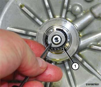
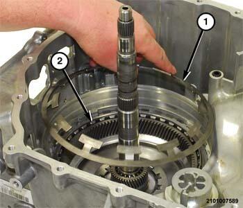
- Install the split roller bearing (1) in position on the input shaft support.
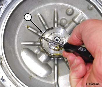
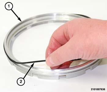
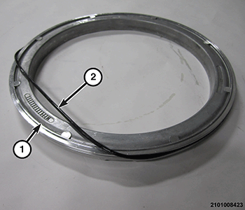
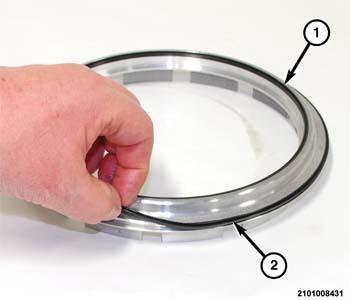
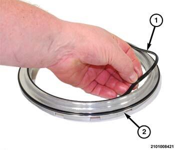
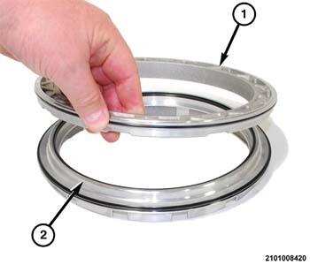
- Install the outer seal-rings (1) in the lands in the input shaft support.
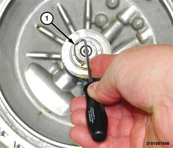
- Install the inner seal-rings (1) in the lands in the input shaft support.
- Install the inner seal (2) on the C-clutch piston (1).
- Install the outer seal (2) on the C-clutch piston (1).
- Install the C-clutch piston (1) in the transmission housing.
- If necessary, use a thin feeler gauge (3) to turn the lip on the seal into the retainer (2) as the piston (1) is pushed downward.
- Place the C-clutch bellville spring (1) in position on the C-clutch piston (2).
- Place the (special tool #10504, Compressor, Spring) (1) over the C-clutch bellville spring (2) at the bottom of the transmission housing (3).
- Position the transmission housing on a suitable arbor press using wooden blocks for support.
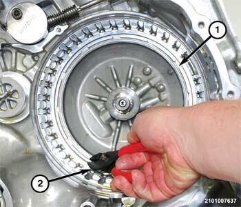
- Place tool (special tool #8228, Installer, Bearing) (3) over the input shaft support (tool 8901 with 10428 legs can also be used), compress the bellville spring to gain access to the snap-ring (1) groove.
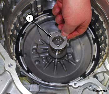
- Install the snap-ring, stepped side down, with the snap-ring ends (1) aligned with machined pocket in the case (2) to hold the C-clutch bellville spring in the transmission housing.
- Remove the transmission housing from the arbor press and position it on a clean work bench. Position wood blocks under transmission to stabilize it for assembly.
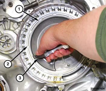
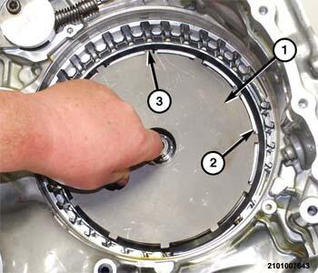
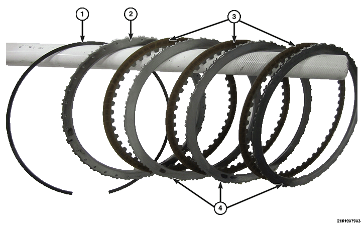
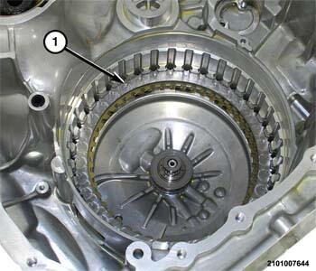
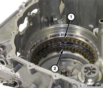
- Install one C-clutch steel plate (4), then install the friction discs (3) alternately separated with steel plates (4) into the transmission housing on top of the C-clutch piston.
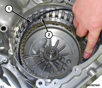
- Install the C-clutch selective reaction plate (1) with raised bosses upward on top of the C-clutch disc and plate pack.
- Install the snap-ring (1) in the groove (2) in the transmission housing.NOTE:
Perform C-clutch measurements to verify that the correct selective reaction plate is installed. Refer to ADJUSTMENTS .
- Perform D-clutch measurements to verify that the correct selective reaction plate (2) is installed. Refer to ADJUSTMENTS .
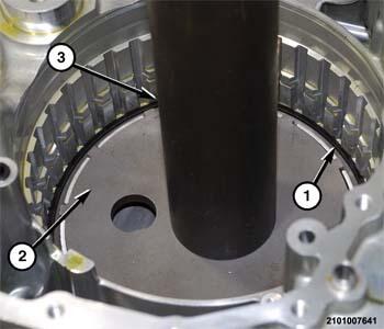
- Install the correct thickness selective reaction plate (2).
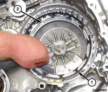
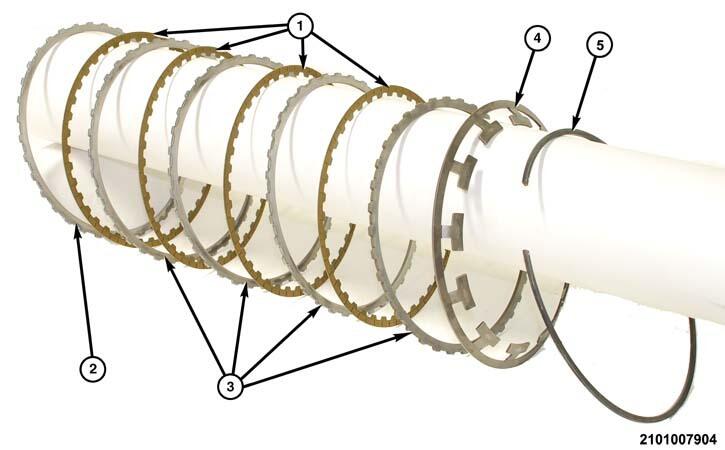
- Starting with a friction plate (1), alternately install the friction (1) and steel plates (3) in to the case.
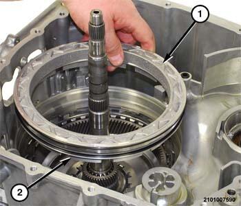
- Install the input shaft rear support selective thrust washer (1).
- Install the thrust bearing (1) onto the input shaft rear support.
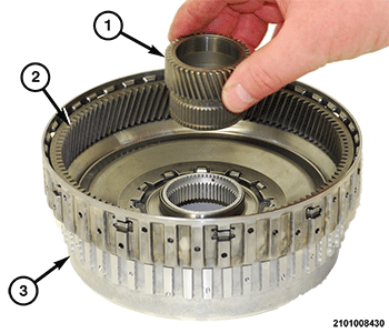
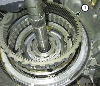
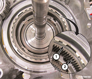
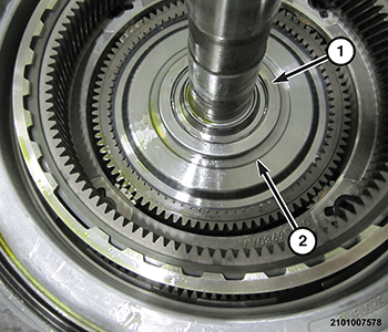
- Align the teeth of the friction discs for the D- and C-clutches (1, 2) to facilitate the installation of the annulus gear 2, D and C clutch hubs, and input shaft assembly.NOTE:
Before final assembly of the annulus gear 2, D and C-clutch hub and input shaft, measure the B-clutch to verify that proper selective reaction plate was installed. Refer to ADJUSTMENTS .
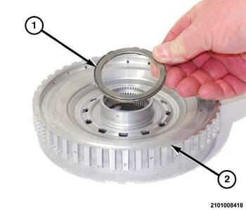
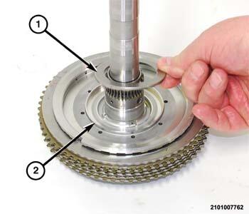
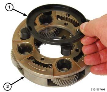
- Place the thrust bearing (1) in position on the C-clutch hub (2).
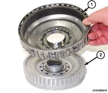
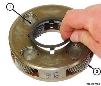
- Place the annulus gear 2, D-clutch hub (1) in position on the C-clutch hub (2).
- Insert the sun gear 1 (1) into annulus gear 2 (2), D and C-clutch hub (3).
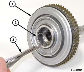
- Turn the annulus gear 2, D and C-clutch hub over and place it on tool (special tool #9611, Plug, Differential End) (2) to hold the sun gear in position.
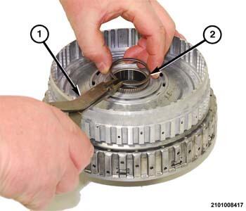
- Using a suitable snap-ring pliers (1), install the snap-ring (2) to hold the sun gear 1 to the annulus gear 2, D and C-clutch hub.
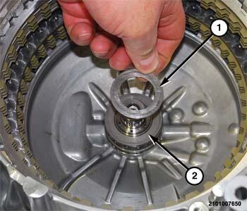
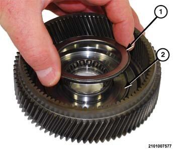
- Insert the number 7 thrust bearing (1) in the C-clutch hub, it should have a snap fit.
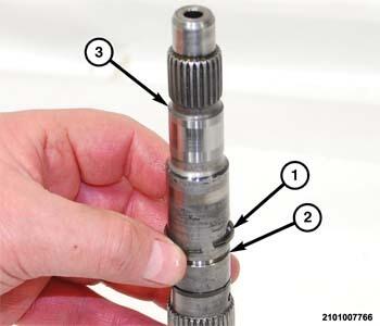
- Install NEW
seal-rings (1) in the lands (2) on the input shaft (3).
- Insert the input shaft into the B-clutch (1) hub.
- Using a suitable snap-ring pliers (3), install the snap-ring (2) to hold the input shaft/dog clutch A to the B-clutch (1) hub.
- Place the thrust bearing (1) on the B-clutch hub (2).
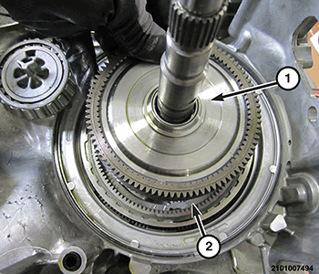
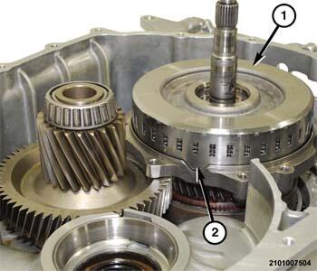
- Install the annulus gear 2, D and C-clutch hub on the input shaft and B-clutch assembly.
- While not allowing the input shaft to slip inward, wriggle the annulus gear 2, D and C-clutch hubs and input shaft assembly (1) until they engage the D and C-clutch discs. If the input shaft slips inward, the B-clutch will come out of its retainer impeding proper installation.NOTE:
A solid audible clunk will be heard if installed correctly.
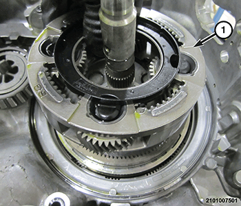
- Place the bellville spring (1) in position on the transmission housing (2).
- Install NEW
O-ring seal (2) in the D-clutch piston retainer (1).
- Install NEW
outer lip seal (2) in the D-clutch piston (1).
- Install NEW
inner lip seal (1) in the D-clutch piston (2).
- Install the D-clutch piston (2) in the retainer (1).
- Place the D-clutch piston (2) and retainer (1) assembly in the transmission housing over the D-clutch bellville spring. The fingers on the D-clutch piston (2) rest against the D-clutch selective reaction plate.
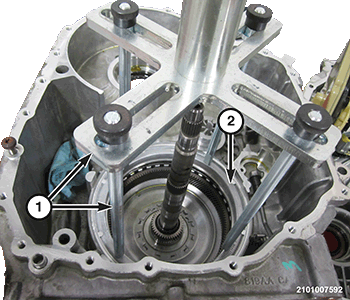
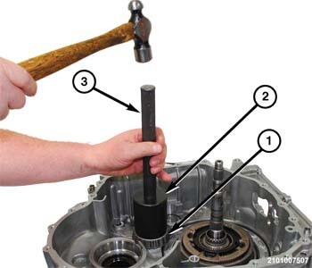
- Position the transmission housing on a suitable arbor press using wooden blocks for support.
- Using Tool (special tool #8901A, Pressing Tool) (with the pressure scale removed) (1) and legs (special tool #10428, Adapter, Pressing Tool), compress the bellville spring to gain access to the snap-ring groove in the transmission housing.
- Install the snap-ring to hold the D-clutch piston retainer (2) into the transmission housing.
- Remove the transmission housing from the arbor press and place the transmission housing on the clean work surface. Use wood blocks to stabilize the transmission.
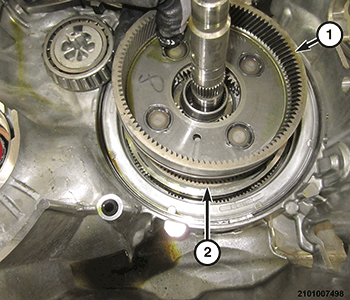
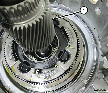
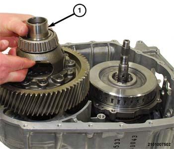
- Insert the carrier gear 1 and 2 annulus gear 2, D-clutch hub and input shaft assembly onto the annulus gear 2, D and C-clutch hub and input shaft assembly.
- Install the NEW
O-ring seal (1) into the carrier gear 1 and 2.
- Install the annulus gear 3 (1) into the carrier gear 1 and 2.
- Install the snap-ring (1) to hold the annulus gear 3 (2) in the carrier gear 1 and 2.
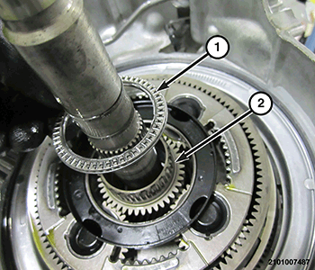
- Place the thrust bearing (1) in position under the annulus gear 1 planetary hub (2).
- Install the annulus gear 1 planetary hub (1) into the carrier gear 1 and 2 (2).
- Place the thrust bearing (1) onto the annulus gear 1 planetary hub (2).
- Install the transfer gear bearing preload shim (1).
- Using tool (special tool #6888, Installer, Seal) (2) and handle (special tool #C-4171, Driver Handle, Universal) (3), install the transfer gear bearing cone (1) in to the transmission housing.
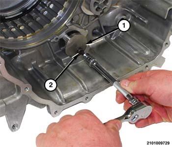
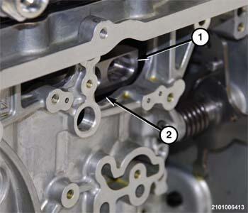
- Position the park rod (2) into the park rod guide (1).
- Position the park rod guide (1) into the housing and tighten the park rod guide bolt (2) to the proper specification. Refer to TECHNICAL SPECIFICATIONS .
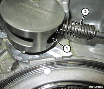
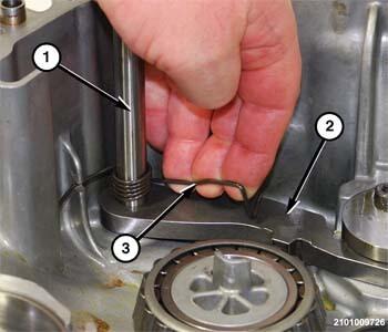
- Position the park pawl (2) into the park rod guide.
- Install the reaction pin (1) through the park pawl (2) and into the case.
- Install the park pawl (2) return spring (3).
- Install the annulus gear 4 (1) in the annulus gear 3 (2).
- Install a NEW
thrust spacer (1) on the underside of the gear 4 planetary pinion carrier (2).
- Install a NEW
thrust spacer (1) on the topside of the gear 4 planetary pinion carrier (2).
- Install the gear 4 planetary pinion carrier (1) into the annulus gear 4.
- Install the sun gear 3 and 4 and Dog Clutch-F (1) in the gear 4 planetary pinion carrier.
- Install the roller type thrust bearing (1) onto the sun gear 3 and 4 and Dog Clutch-F (2).
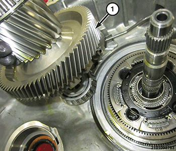
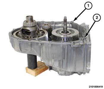
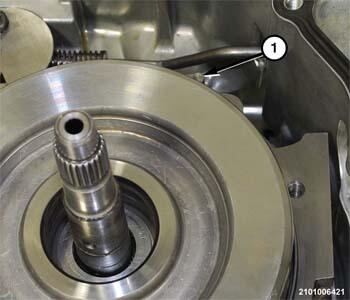
- If necessary, replace the bearings and races on the transfer gear (1).
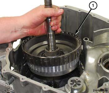
- Install the transfer gear (1) into the transmission housing.
- Install the output gear support (1) into the gear 4 planetary pinion carrier (2).
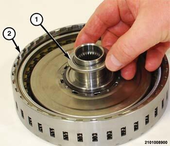
- Install the E-clutch hub and shaft (1) in the output gear support (2).
- Install the thrust bearing (1) on the E-clutch (2) hub.NOTE:
Before installing the E-clutch, use a suitable screwdriver to align the grooves in the friction discs.
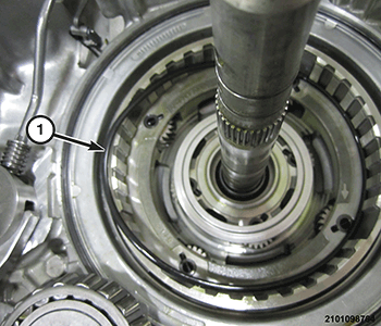
- Wriggle the E-clutch (1) until all of the friction discs are fully engaged on the E-clutch hub and shaft.NOTE:
When the E-clutch (1) is fully seated the gap (2) will be very small between the E-clutch retainer and the output gear support.
NOTE:If a new differential (1) or transmission housing are being used, measurements must be performed to determine correct thickness for the bearing preload shims. Refer to STANDARD PROCEDURES . If the bearings and races are replaced, the factory installed preload shims do not require replacement.
- If necessary, replace the bearings and races on the differential (1).
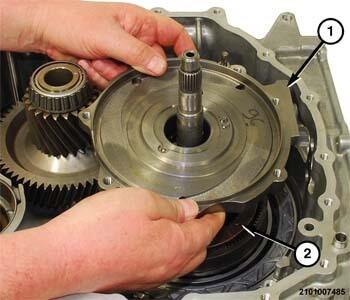
- Install the differential assembly (1) into the transmission housing.
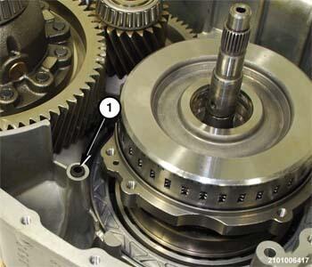
- Install a NEW
seal (1) in the port in the transmission housing.
- Install a NEW gasket (1) on the sealing surface of the transmission housing (2).
- If necessary, replace the output seals and the impeller hub seal.
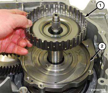
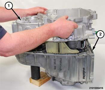
- Guide the bellhousing (1) downward over the input and output shafts and onto the transmission housing (2).
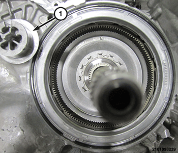
- Rotate the output gear clockwise to assure guide pin (1) alignment.
- Rotate the output gear support (1) through the window (2) behind the valve body until the guide pin engages the receptacle hole in the bellhousing.
- Engage the guide pins in the transmission housing into the receptacle holes in the bellhousing to assure proper alignment.
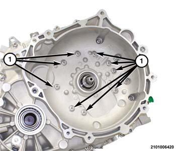
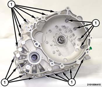
- Install several bolts to hold the bell housing to the transmission housing. Tighten the bolts hand tight.
- Position the transmission on the bench with the bellhousing facing outward.
- Install the bolts (1) with NEW
seal washers to hold the bellhousing to the output gear support and tighten to the proper torque specifications. Refer to TECHNICAL SPECIFICATIONS .
- Install the bolts (1) to hold the bellhousing to the transmission housing and tighten to the proper torque specifications. Refer to TECHNICAL SPECIFICATIONS .
- Install NEW O-rings on both ends of the fluid transfer tubes.
- Install the fluid transfer tubes (1) in the transmission housing.
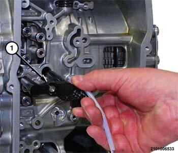
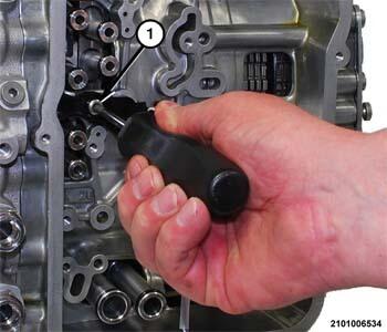
- Insert the speed sensors (1) into the transmission with the wire harness connected.
- Install the speed sensor screw (1) to hold the speed sensors to the transmission housing and tighten to the proper torque specifications. Refer to TECHNICAL SPECIFICATIONS .
- Place the Transmission Range Sensor (TRS) (1) in position on the transmission with the wire harness connected.
- Install the TRS screw (1) to hold the TRS to the transmission housing and tighten to the proper torque specifications. Refer to TECHNICAL SPECIFICATIONS .
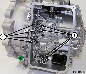
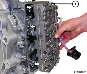
- Place the valve body (1) in position on the transmission.
- Place the transmission solenoid wire harness connector (2) in position on the solenoids.
- Press the transmission solenoid wire harness connector (2) inward to engage the terminals on the solenoids.
- Install the screws (1) to hold the valve body wire harness connector (2) to the valve body and solenoids and tighten to the proper torque specifications. Refer to TECHNICAL SPECIFICATIONS .
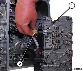
- Connect the wire harness connector (2) to the transmission fluid pressure sensor (1).
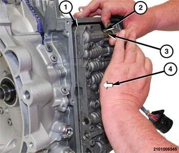
- Turn the valve body (1) over and align with the fluid transfer tubes.
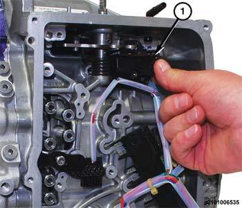
- Guide the manual lever cam (2) into the slot (3) on the manual valve.
- Firmly press (4) the valve body (1) inward until the O-rings on the fluid transfer tubes engage into receptacle holes on the valve body.
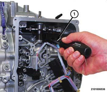
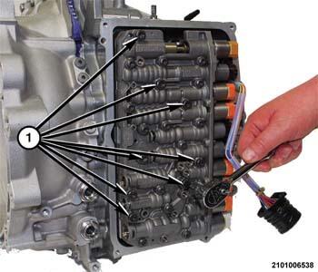
- Install the valve body bolts (1) to hold the valve body to the transmission housing and tighten to the proper torque specifications. Refer to TECHNICAL SPECIFICATIONS .NOTE:
A light coating of assembly lube can be applied to the O-ring seals (2) of the valve body wire harness connector to ease installation.
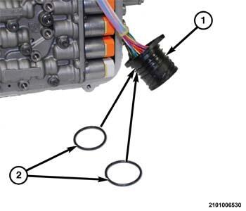
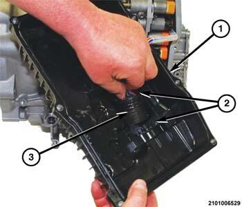
- Install NEW
O-ring seals (2) on the valve body wire harness connector (1).
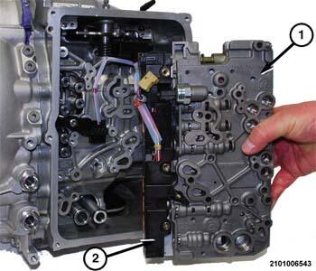
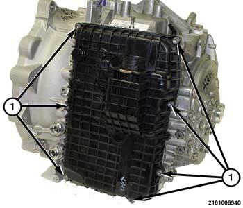
- Place the valve body cover pan (1) in position on the transmission.NOTE:
Be certain that the flat side (2) on the valve body wire harness connector (3) is aligned with the flat spot on the valve body cover pan (1).
- Insert the valve body wire harness connector (3) into the opening on the inside of valve body cover pan (1).
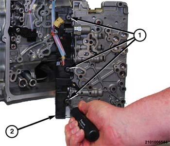
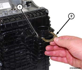
- Press the transmission solenoid connector inward until the retainer clip groove (1) is exposed on the outside of the valve body cover pan.
- Install the clip (2) to hold the transmission solenoid connector in the valve body cover pan.NOTE:
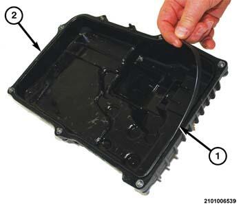
The gasket seal (1) and valve body cover pan (2) are replaced together. If either are damaged the valve body cover pan/gasket must be replaced as an assembly.
- Make sure the gasket seal (1) is in the groove around the sealing surface of the valve body cover pan (2).
- Install the valve body cover pan and valve body cover pan bolts (1) to hold the valve body cover pan to the transmission housing and tighten to the proper torque specifications. Refer to TECHNICAL SPECIFICATIONS .