B-Clutch Assembly
Always wear safety glasses when cleaning, disassembling and assembling the transmission/transaxle. Contents of the transmission/transaxle can become projectiles (e.g., springs, snap-rings, as well as metal and other debris). Failure to wear safety glasses may result in severe personal injury.
Clean the B-clutch components with suitable solvent and blow them dry with regulated 344 kPa (50 psi) shop air. Position all of the B-clutch components on a clean work surface in preparation for assembly.
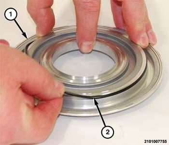
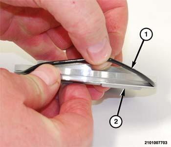
- Lubricate the O-ring seal (2) with clean transmission fluid and install it on the B-clutch piston (1).
- Lubricate the O-ring seal (1) with clean transmission fluid and install it on the B-clutch shim support (2).
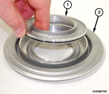
- Install the shim support (1) in the B-clutch piston (2).
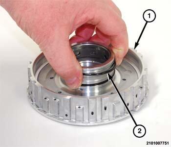
- Install New O-ring seals (2) in the B-clutch hub (1).
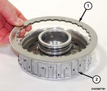
- Install the belleville spring (2) in the B-clutch hub (1).NOTE:
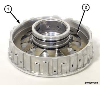
The reaction plate is select fit, the B-clutch must be fully assembled to measure for the correct reaction plate.
- Install the reaction plate (1) on the B-clutch hub (2).NOTE:
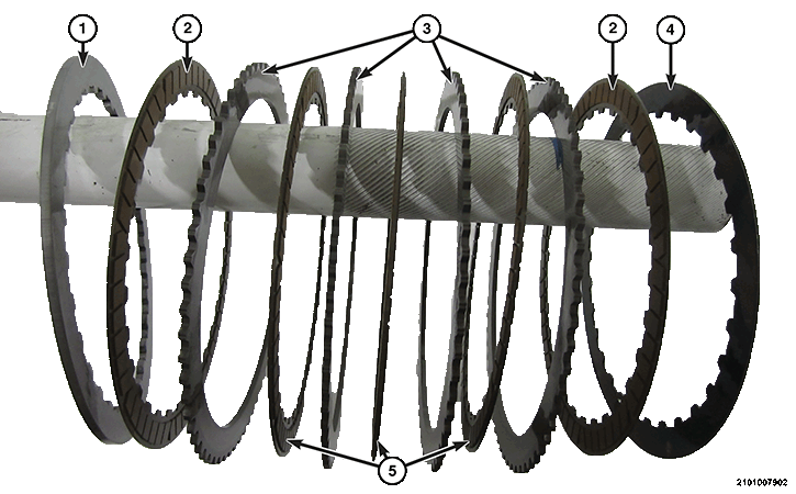
The first and last friction discs (2) have friction material only on one side. They are not interchangeable with the double sided friction discs (5).
NOTE:Diesel and V-6 gas engine clutch pack shown in illustration above, 4 cylinder gas engines will have one less double sided friction disc (5) and steel plate (3).
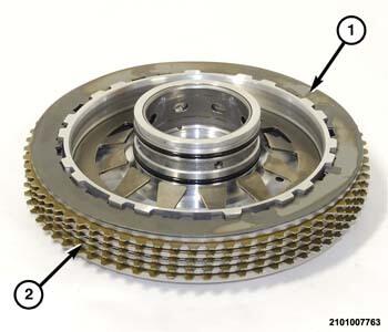
- In alternating sequence, install the B-clutch friction plates (2 and 5) and steel plates (3) On the B-clutch hub.
- Install the wave spring plate (1) on the B-clutch hub.
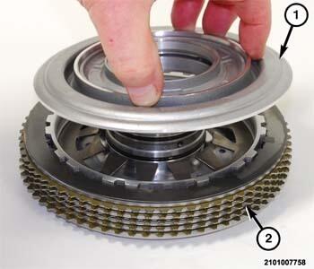
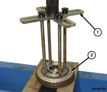
- Install the piston (1) on the B-clutch (2).
- Using tool (special tool #8901A, Pressing Tool) (with pressure scale removed) (1) and legs (special tool #10428, Adapter, Pressing Tool), compress the B-clutch (2) piston to gain access to the snap-ring.
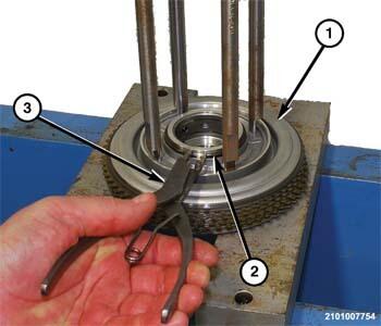
- Using suitable snap-ring pliers (3), install the snap-ring (2) in the B-clutch (1) hub.
- Before installing the input shaft/dog A-clutch, measure the B-clutch to determine if the proper select reaction plate was installed. Refer to ADJUSTMENTS
.
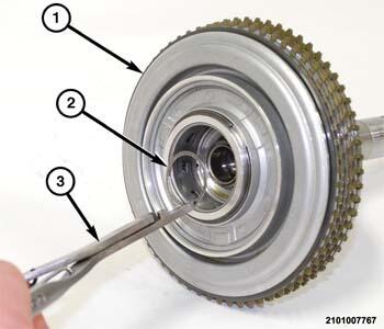
- Insert the input shaft/dog A-clutch assembly into the B-clutch assembly (1).
- Using suitable snap-ring pliers (3), install the snap-ring (2) to hold the input shaft in the B-clutch assembly (1).