Removal And Installation: Installation
Be certain to adjust the refrigerant oil level when servicing the A/C refrigerant system. Failure to properly adjust the refrigerant oil level will prevent the A/C system from operating as designed and can cause serious A/C compressor damage.
When replacing multiple A/C system components, see the Refrigerant Oil Capacities chart to determine how much oil should be added to the refrigerant system. Refer to STANDARD PROCEDURE - REFRIGERANT OIL LEVEL .
Replacement of the refrigerant line seals and gaskets is required anytime a refrigerant line is disconnected. Failure to replace the rubber O-ring seals, metal gaskets or washer seals may result in a refrigerant system leak.
- Remove the tape or plugs from the opened refrigerant line fittings and the expansion valve and compressor ports.
- Position the A/C line assembly into the engine compartment.
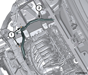
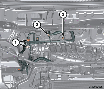
- Engage the A/C line assembly to the bulkhead studs. Install the A/C line assembly to bulkhead nuts (3). Tighten the nuts securely.
- Connect the A/C line assembly to the front expansion valve. Install and tighten the A/C line assembly to front expansion valve nut (2) to the proper. Refer to TECHNICAL SPECIFICATIONS .
- On models equipped with the HVACR system, connect the A/C suction and liquid extension line to the A/C line assembly and tighten the extension line fitting nuts (1) to the proper. Refer to TECHNICAL SPECIFICATIONS .
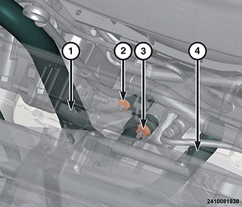
- Install and tighten the two A/C line assembly to body fasteners (1) to the proper. Refer to TECHNICAL SPECIFICATIONS .
- Install the right engine insulator. Refer to INSULATOR, ENGINE MOUNT, RIGHT, REMOVAL AND INSTALLATION .
- Raise and support the vehicle. Refer to HOISTING, STANDARD PROCEDURE
.NOTE:
Lubricate NEW rubber O-ring seals with clean refrigerant oil and install them and NEW gaskets onto the refrigerant line fittings. Use only the specified O-rings as they are made of a special material for the R-1234yf system. Use only refrigerant oil of the type recommended for the A/C compressor in the vehicle.
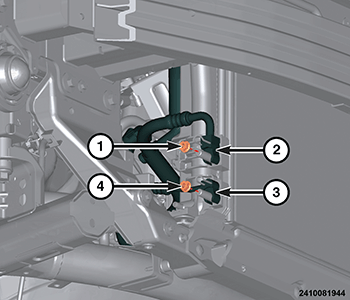
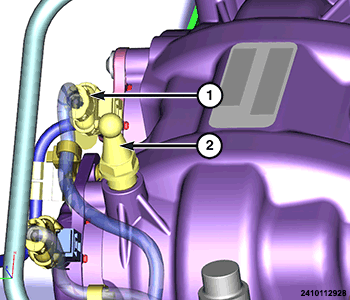
- Position the A/C liquid line (3) onto the condenser. Install and tighten the A/C liquid line to condenser nut (4) to the proper. Refer to HOISTING, STANDARD PROCEDURE
.NOTE:
Lubricate NEW rubber O-ring seals with clean refrigerant oil and install them and NEW gaskets onto the refrigerant line fittings. Use only the specified O-rings as they are made of a special material for the R-1234yf system. Use only refrigerant oil of the type recommended for the A/C compressor in the vehicle.
- Position the A/C suction line (1) to the compressor. Install and tighten the A/C suction line to compressor nut (3) to the proper. Refer to HOISTING, STANDARD PROCEDURE .
- Install the front belly pan. Refer to BELLY PAN, FRONT, REMOVAL AND INSTALLATION .
- Install the front engine belly pan. Refer to BELLY PAN, ENGINE
.
- Install the right front fascia support bracket (2).
- Install the right front shock tower brace (1).
- Connect the Antilock Brake System (ABS) Module wire harness connector.
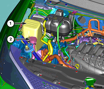
- Install the washer reservoir neck (2).
- Install the ABS Module cover (1).
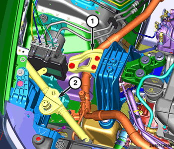
- Install the fuel vapor tube assembly ball stud (2) and connect the cam phaser actuator wire harness connector (1).
- Install the coolant recovery bottle. Refer to BOTTLE, PRESSURIZED COOLANT, REMOVAL AND INSTALLATION .
- Install cylinders 1 and 3 ignition coils. Refer to COIL, IGNITION, REMOVAL AND INSTALLATION .
- Install the Bank 1/Solenoid 1 variable valve lift solenoid. Refer to SOLENOID, VARIABLE VALVE LIFT, REMOVAL AND INSTALLATION .
- Install the air cleaner resonator. Refer to RESONATOR, AIR CLEANER, REMOVAL AND INSTALLATION .
- Connect the negative battery cable. If equipped with an Intelligent Battery Sensor (IBS), connect the IBS connector.
- Charge the refrigerant system. Refer to PLUMBING, FRONT, STANDARD PROCEDURE .