Removal And Installation: Installation
CAUTION:
Be certain to adjust the refrigerant oil level when servicing the A/C refrigerant system. Failure to properly adjust the refrigerant oil level will prevent the A/C system from operating as designed and can cause serious A/C compressor damage.
NOTE:
When replacing multiple A/C system components, see the Refrigerant Oil Capacities chart to determine how much oil should be added to the refrigerant system. Refer to STANDARD PROCEDURE - REFRIGERANT OIL LEVEL .
NOTE:
Replacement of the refrigerant line O-ring seals and gaskets is required anytime a refrigerant line is disconnected. Failure to replace the rubber O-ring seals and metal gaskets may result in a refrigerant system leak.
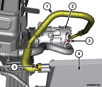
- Position the A/C discharge line (1) into the engine compartment.
- Remove the tape or plugs from the opened refrigerant line fittings and the compressor and condenser ports.
- Lubricate NEW rubber O-ring seals with clean refrigerant oil and install them and NEW gaskets on the discharge line fittings. Use only the specified O-rings as they are made of a special material for the system. Use only refrigerant oil of the type recommended for the A/C compressor in the vehicle.
- Combine the A/C suction line and the A/C discharge line (1). Connect the lines to the A/C compressor (2).
- Install the bolt (3) that secures the A/C discharge line (1) and A/C suction line to the A/C compressor and tighten to the proper torque specifications. Refer to TECHNICAL SPECIFICATIONS .
- Connect the A/C discharge line (1) to the condenser (4).
- Install the bolt (5) that secures the A/C discharge line (1) to the A/C condenser (4) and tighten to the proper torque specifications. Refer to TECHNICAL SPECIFICATIONS .
- Install the front belly pan. Refer to BELLY PAN, FRONT, REMOVAL AND INSTALLATION .
- Install the front engine belly pan. Refer to BELLY PAN, ENGINE, REMOVAL AND INSTALLATION .
- Connect the negative battery cable. If equipped with an Intelligent Battery Sensor (IBS), connect the IBS connector.
- Evacuate the refrigerant system. Refer to PLUMBING, FRONT, STANDARD PROCEDURE .
- Charge the refrigerant system. Refer to PLUMBING, FRONT, STANDARD PROCEDURE .