Theory Of Operation
In order for the Powertrain Control Module (PCM) to ensure that the Accelerator Pedal does not become stuck in any way while the vehicle is driven, the PCM monitors the APP Sensor voltage and the brake input. A combination of a stationary APP Sensor voltage reading and a brake pedal input can be used to diagnose an improperly functioning Accelerator Pedal. Since the Brake Switch input is used to validate the Accelerator Pedal input, it is important to understand the operation of the diagnostic monitor.
Accelerator Pedal Position (APP) Sensor applications today use Induction/Hall Sensors (non-contact).
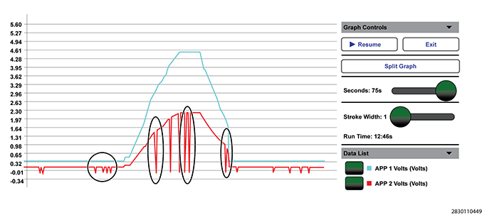
The APP Sensor contains two independent three wire sensors. Each sensor provides independent pedal position signals to the Powertrain Control Module (PCM). The APP Sensors 1 and 2 are integrated into one assembly located at the pedal assembly. Each sensor has a 5 volt reference circuit, a low reference circuit, and a signal circuit. The Powertrain Control Module (PCM) reads the two signals individually and then compares the two signals as a redundant check of the pedal position. The APP 1 signal will fluctuate between 0 volts and 5.0 volts. The APP 2 signal will fluctuate between 0 volts and 2.5 volts. The fluctuation of the two sensors should move proportionately. When operating properly, the voltage reading of the APP 2 will always be approximately half of the voltage reading of the APP 1.
The signal for APP 2 is also used by the PCM for an internal ground check. This test runs a couple of times per second and is the reason why the APP 2 signal spikes to ground regularly during normal operation. If graphing the APP 1 and APP 2 signals for diagnostic purposes, view the figure below to see how the signals will look on a normally functioning APP system.