Theory Of Operation
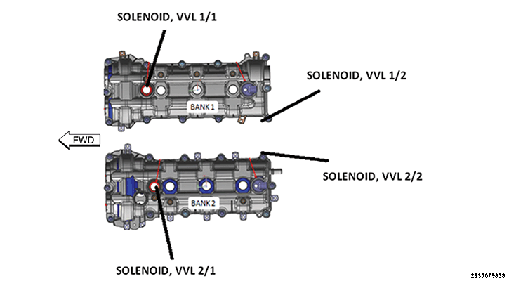
There are four Variable Valve Lift (VVL) Solenoids that control the operation of the Intake Rocker Arms for all six cylinders. See the figure and table below for the VVL Solenoid locations and cylinder control:
| VVL SOLENOID | PHYSICAL LOCATION | CYLINDERS CONTROLLED | RELATED FAULT CODES |
|---|---|---|---|
| VVL SOLENOID 1/1 | BANK 1 FRONT SOLENOID | CYLINDER 1 INTAKE VALVES | P1050 / P1051 / P1052 / P1070 |
| VVL SOLENOID 1/2 | BANK 1 REAR SOLENOID | CYLINDERS 3 AND 5 INTAKE VALVES | P1053 / P1054 / P1055 / P1071 |
| VVL SOLENOID 2/1 | BANK 2 FRONT SOLENOID | CYLINDER 2 INTAKE VALVES | P1056 / P1057 / P1058 / P1072 |
| VVL SOLENOID 2/2 | BANK 2 REAR SOLENOID | CYLINDERS 4 AND 6 INTAKE VALVES | P1059 / P105A / P105B / P1073 |
| These faults set when the PCM detects that one or more rockers are stuck in high lift or low lift mode. They are not specific to any of the solenoids. To determine which cylinder is being affected and setting the fault, the intrusive VVL service routine in the scan tool should be run to help determine the affected cylinder(s). | P105C / P105D | ||
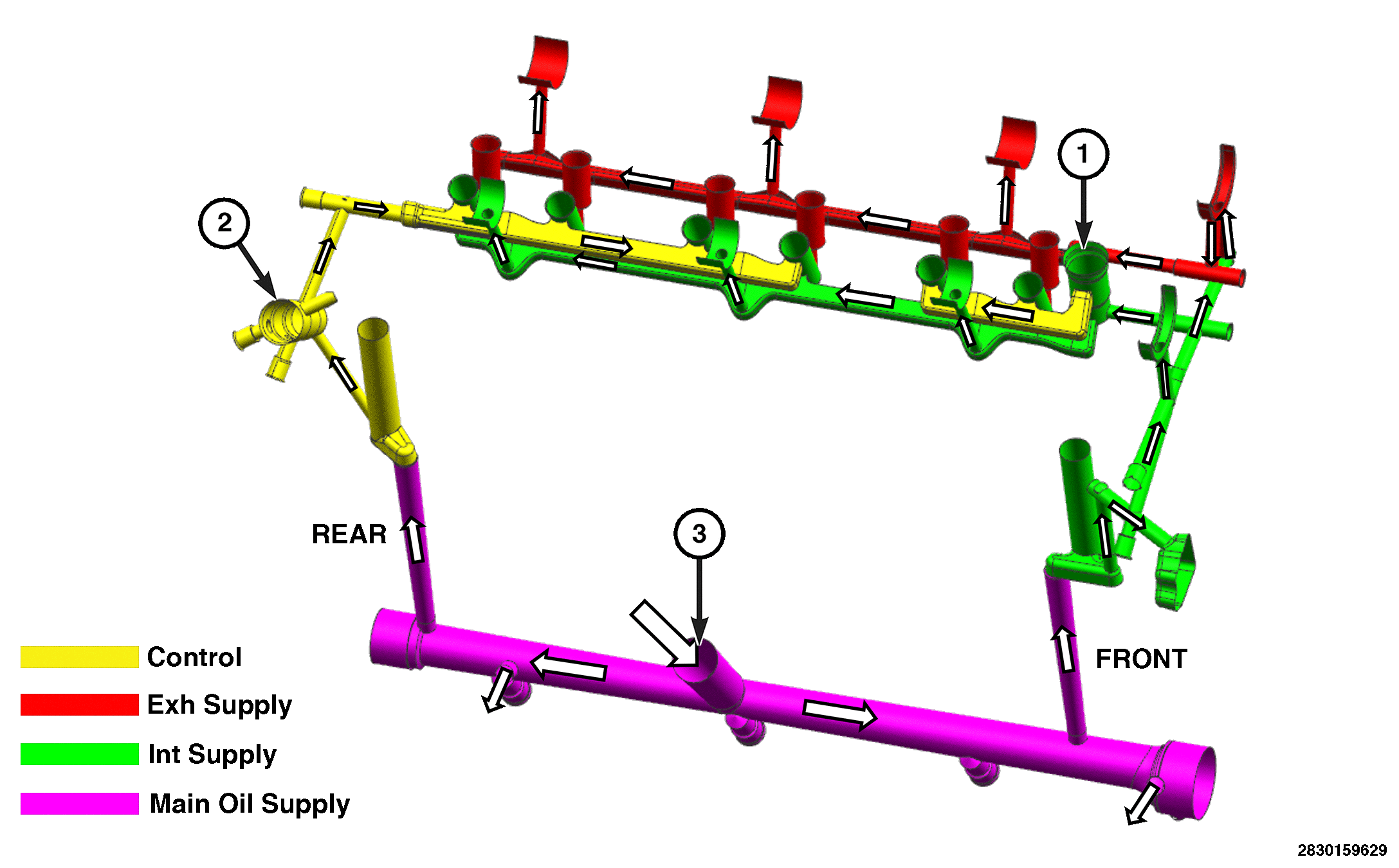
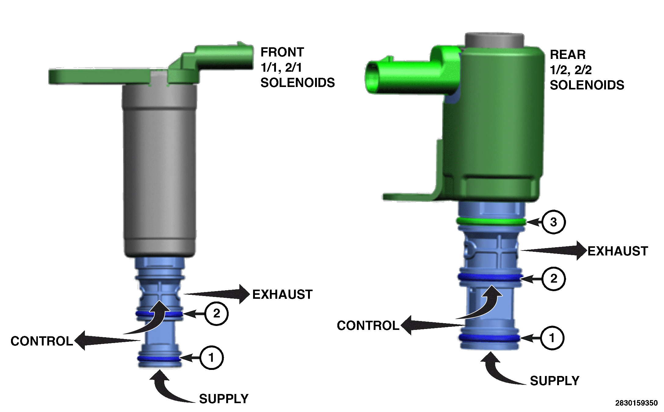
GENERAL OPERATION: The VVL System is designed to vary the lift and duration of the Intake Valves, to maximize efficiency and engine torque, depending on engine operation. The VVL System consists of 2 step Intake Rocker Arms that are capable of operating in High Lift or Low Lift mode. The PCM energizes and de-energizes the four VVL Solenoids to control the engine oil pressure to the Rocker Arms, controlling low lift and high lift operation. The O-rings on the solenoids prevent oil leakage between passages. The Supply O-ring (1) prevents the pressurized supply oil from entering the control passage when the solenoid is de-energized (off). The Control O-ring (2) prevents the oil from entering the exhaust passage when the solenoid is energized (on). Only the rear solenoid has an Exhaust O-ring (3) preventing an external oil leak. The front solenoid has an external seal to prevent external oil leakage. If an O-ring is damaged or missing it can cause a Rocker Arm to stick in low lift or high lift mode.
- To enter Low Lift Mode the PCM provides 12.0 volts to the VVL Solenoid to energize the solenoid. When energized the VVL Solenoid opens allowing the supply oil pressure entering the bottom to pass through the solenoid to the control oil passage and Rocker Arm. The pressurized oil pushes against the springs in the lock pins forcing the pins to retract. This allows the center of the Rocker Arm to move down freely and operate in Low Lift Mode. It takes approximately 20.0 psi of engine oil pressure at the Rocker Arm to overcome the springs in the lock pins.
- To re-enter High Lift Mode the PCM de-energizes the VVL Solenoid. The solenoid closes and the pressurized oil in the control passage passes through the VVL Solenoid to the exhaust passage. When the oil pressure is relieved the spring loaded lock pin extends keeping the center of the Rocker Arm in the High Lift position. The Rocker Arms default to High Lift mode when no oil pressure is present.
| 1 | Front VVL Solenoid location |
| 2 | Rear VVL Solenoid location |
| 3 | Oil supply from Oil Filter to the main oil gallery |