Left Cylinder Head: Installation
- If removed, install the ignition coil capacitor and the engine wire harness retainer bracket, then tighten to the proper torque specification. Refer to TECHNICAL SPECIFICATIONS .
- Clean and prepare the gasket sealing surfaces of the cylinder head and block. Refer to STANDARD PROCEDURE .CAUTION:
Non-compressible debris such as oil, coolant or RTV sealants that are not removed from bolt holes can cause the aluminum casting to crack when tightening the bolts.
CAUTION:When cleaning cylinder head and cylinder block surfaces, DO NOT use a metal scraper because the surfaces could be cut or ground. Use ONLY a wooden or plastic scraper.
- Clean out the cylinder head bolt holes in the engine block.WARNING:
The multi-layered steel head gaskets have very sharp edges that could cause personal injury if not handled carefully.
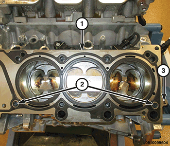
CAUTION:The installation of the cylinder head gaskets are not interchangeable between the left and right cylinder heads. They are clearly marked (3) with "R" for right and "L" for left. They must be applied on a dry surface, without the use of any adhesives.
- Position the new cylinder head gasket (1) on the locating dowels (2).CAUTION:
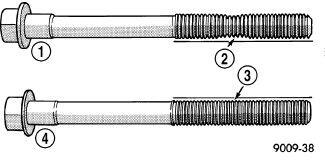
The cylinder head bolts are tightened using a torque plus angle procedure. The bolts must be examined BEFORE reuse. If the threads are necked down the bolts must be replaced.
- Check cylinder head bolts for necking by holding a scale or straight edge against the threads. If all the threads do not contact the scale (2) the bolt must be replaced.
- Position the cylinder head onto the cylinder block. Make sure the cylinder head seats fully over the locating dowels.NOTE:
Do not apply any additional oil to the bolt threads.
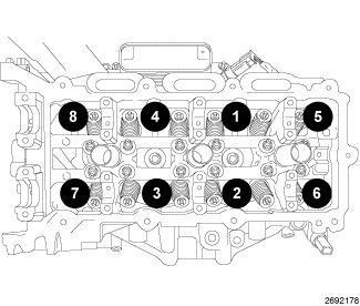
- Install the eight cylinder head bolts finger tight.NOTE:
For engine builds using a new block follow steps 1-9. For engine re-builds (reuse block) follow step 6-9.
- Tighten the cylinder head bolts in the sequence shown, following this 9 step torque plus angle method. The torque sequence must be used for each step. Tighten according to the following torque values:
- Step 1: All to 30 N.m (22 ft. lbs.)
- Step 2: All to 45 N.m (33 ft. lbs.)
- Step 3: Re-tighten all to 45 N.m (33 ft. lbs.)
- Step 4: All + 125° Turn (optional angle if 125° rotation cannot be accomplished in one motion; tighten all by turning 35° followed by tightening all by turning 90°) Do not use a torque wrench for this step.
- Step 5: Loosen all fasteners in reverse of sequence shown
- Step 6: All to 30 N.m (22 ft. lbs.)
- Step 7: All to 45 N.m (33 ft. lbs.)
- Step 8: Re-tighten all to 45 N.m (33 ft. lbs.)
- Step 9: All + 130° Turn (optional angle if 130° rotation cannot be accomplished in one motion; tighten all by turning 40° followed by tightening all by turning 90°) Do not use a torque wrench for this step.
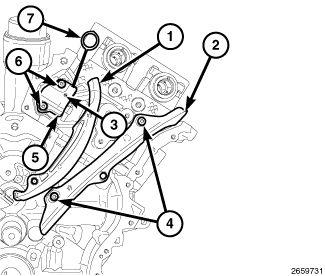
- Install the LH cam chain guide (2) with two bolts (4) and tighten the bolts (4) to the proper torque specification. Refer to TECHNICAL SPECIFICATIONS .
- Install the LH cam chain tensioner (5) to the cylinder head with two bolts (6) and tighten the bolts (6) to the proper torque specification. Refer to TECHNICAL SPECIFICATIONS .
- Reset the LH cam chain tensioner (5) by lifting the pawl (3), pushing back the piston and installing Tensioner Pin (special tool #8514A, Pins, Tensioner) (7)
Refer to VALVE TIMING, STANDARD PROCEDURE .
- Install the LH tensioner arm (1).
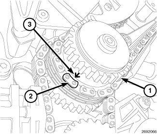
- Drape the left side cam chain onto the idler sprocket (1) so that the arrow (3) is aligned with the plated link (2) on the cam chain.CAUTION:
Always reinstall timing chains so that they maintain the same direction of rotation. Inverting a previously run chain on a previously run sprocket will result in excessive wear to both the chain and sprocket.
- If removed, install the hydraulic lifters. Refer to ROCKER ARM, VALVE, REMOVAL AND INSTALLATION .NOTE:
If the rocker arms and hydraulic lifters are being reused, reassemble them into their original locations.
- Install the rocker arms and camshafts. Refer to CAMSHAFT, ENGINE, REMOVAL AND INSTALLATION .CAUTION:
Do not rotate the camshafts more than a few degrees independently of the crankshaft. Valve to piston contact could occur resulting in possible valve damage. If the camshafts need to be rotated more than a few degrees, first move the pistons away from the cylinder heads by rotating the crankshaft counterclockwise to a position 30° before-top-dead-center. Once the camshafts are returned to their top-dead-center position, rotate the crankshaft clockwise to return the crankshaft to top-dead-center.
- Remove the Tensioner Pin (special tool #8514A, Pins, Tensioner) from the LH cam chain tensioner.
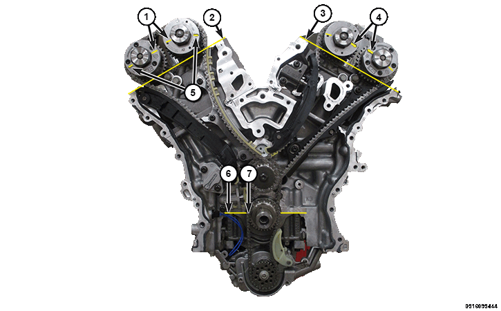
- Rotate the crankshaft clockwise two complete revolutions stopping when the dimple (7) on the crankshaft is aligned the with the block/bearing cap junction (6).
- While maintaining this alignment, verify that the arrows on the left side cam phasers (4) point toward each other and are parallel to the valve cover sealing surface (3) and that the right side cam phaser arrows (5) point away from each other and the scribe lines (5) are parallel to the valve cover sealing surface (2).
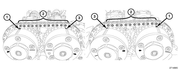
- There should be 12 chain pins (2) between the exhaust cam phaser triangle marking (1) and the intake cam phaser circle marking (3).
- If the engine timing is not correct. Refer to CHAIN AND SPROCKETS, TIMING, REMOVAL AND INSTALLATION .
- Install the engine timing cover and cylinder head covers. Refer to COVER(S), ENGINE TIMING, REMOVAL AND INSTALLATION .
- Install the spark plugs. Refer to SPARK PLUG, REMOVAL AND INSTALLATION .
- Install the left side catalytic converter. Refer to CONVERTER, CATALYTIC, REMOVAL AND INSTALLATION
.
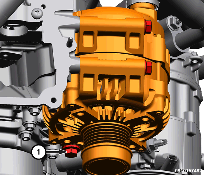
- Install the generator mounting bolts (1) and tighten to the proper torque specification. Refer to TECHNICAL SPECIFICATIONS .
- Install the heater core return hose onto the water pump bypass.
- Install the Exhaust Gas Recirculation (EGR) cooler and upper intake manifold support bracket with lower bolt. Refer to COOLER, EXHAUST GAS RECIRCULATION (EGR), REMOVAL AND INSTALLATION .
- Install the upper and lower intake manifolds. Refer to MANIFOLD, INTAKE, REMOVAL AND INSTALLATION .
- Install a new oil filter and fill the engine crankcase with the proper oil to the correct level. Refer to OIL, STANDARD PROCEDURE .
- Fill the cooling system. Refer to STANDARD PROCEDURE .
- Connect the negative battery cable.
- Run the engine until it reaches normal operating temperature. Check cooling system for correct fluid level. Refer to STANDARD PROCEDURE .
The Cam/Crank Variation Relearn procedure must be performed using the scan tool anytime there has been a repair/replacement made to a powertrain system, for example: flywheel, valvetrain, camshaft and/or crankshaft sensors or components.