Right Cylinder Head Cover: Removal
NOTE:
The magnetic timing wheels must not come in contact with magnets (pickup tools, trays, ect.) or any other strong magnetic field. This will destroy the timing wheels ability to correctly relay camshaft position to the camshaft position sensor.
- Disconnect and isolate the negative battery cable.
- Remove the engine cover and bracket. Refer to COVER, ENGINE, REMOVAL AND INSTALLATION .
- Remove the air cleaner body. Refer to BODY, AIR CLEANER, REMOVAL AND INSTALLATION .
- Remove the heater hose assembly from the right side cylinder head cover and position aside.NOTE:
Do not open cooling system, position the hose assembly aside.
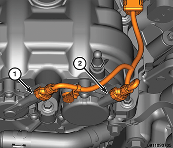
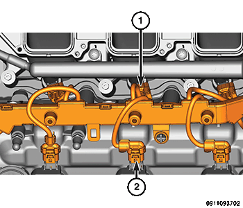
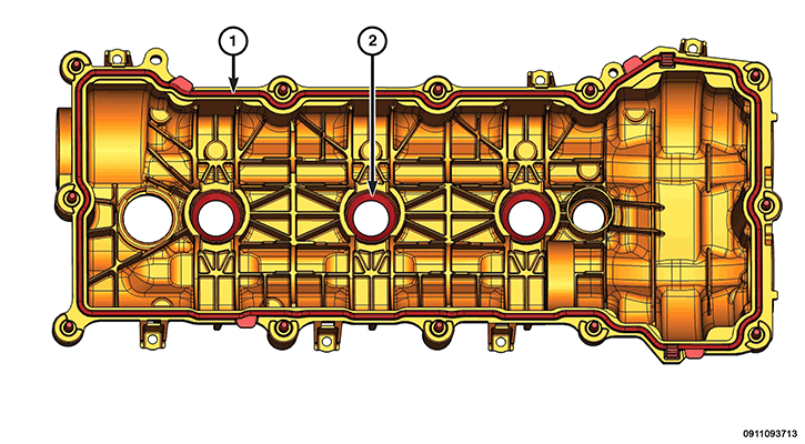
- Disconnect the wire harness connectors (1 and 2) from the variable valve timing solenoids on the right cylinder head cover.NOTE:
Mark the variable valve timing solenoid connectors with a paint pen or equivalent so that they may be reinstalled in their original locations.
- Disengage the wire harness retainers from the right cylinder head cover.
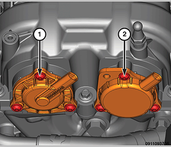
- Mark the variable valve timing solenoids (1 and 2) with a paint pen or equivalent so that they may be reinstalled in their original locations.
- Remove the variable valve timing solenoids. Refer to SOLENOID, VARIABLE VALVE TIMING, REMOVAL AND INSTALLATION
.
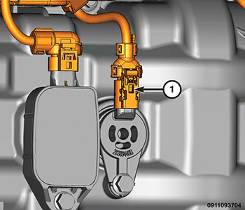
- Disconnect the Variable Valve Lift (VVL) solenoid wire harness connector (1).
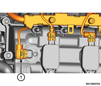
- Disconnect the wire harness connector (1) from the right side Camshaft Position (CMP) sensor.
- Disconnect the injector (1) and ignition (2) wire harness retainers and position the wire harness aside.
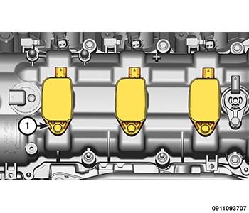
- Remove the right side ignition coils (1). Refer to COIL, IGNITION, REMOVAL AND INSTALLATION
.
- Remove the camshaft position sensor (1). Refer to SENSOR, CAMSHAFT POSITION, REMOVAL AND INSTALLATION
.
- Remove the VVL solenoid (1) from the right cylinder head cover. Refer to SOLENOID, VARIABLE VALVE LIFT, REMOVAL AND INSTALLATION .
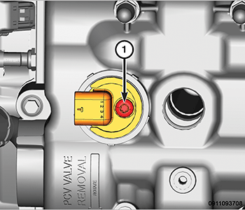
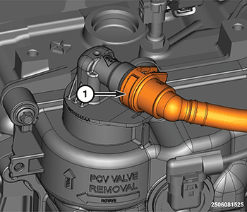
- Push in on the tab (1) to release the quick disconnect and remove the hose from the PCV valve.
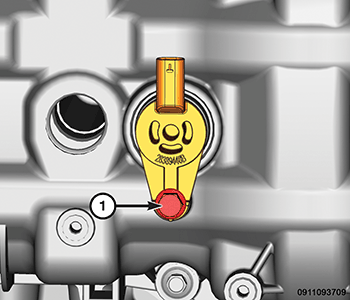
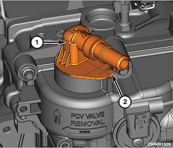
- Release the lock tab (2) and turn the PCV valve (1) clockwise and pull out to remove from the right cylinder head cover.
- Remove the resonator and fuel vapor tube mounts (1) from the cylinder head cover.
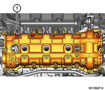
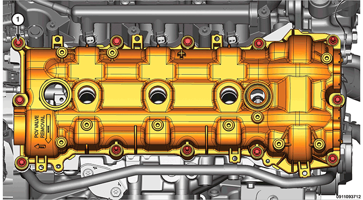
- Loosen the cylinder head cover mounting bolts (1) and remove the cylinder head cover.
- Remove and discard the cylinder head cover gasket (1).
- The spark plug tube seals (2) can be reused if not damaged.CAUTION:
Do not use oil based liquids, wire brushes, abrasive wheels or metal scrapers to clean the engine gasket surfaces. Use only isopropyl (rubbing) alcohol, along with plastic or wooden scrapers. Improper gasket surface preparation may result in engine fluid leakage.
- Remove all residual sealant from the cylinder head, timing chain cover and cylinder head cover mating surfaces. Refer to STANDARD PROCEDURE .