Removal And Installation: Removal
To remove the crankshaft from the engine, the engine must be removed from the vehicle.
- Remove the engine. Refer to REMOVAL AND INSTALLATION .
- Remove the cylinder head covers, spark plugs, oil pan, engine timing cover, timing chain and sprockets. Refer to CHAIN AND SPROCKETS, TIMING, REMOVAL AND INSTALLATION .
- Remove the flexplate and the rear crankshaft oil seal. Refer to SEAL, CRANKSHAFT OIL, REAR, REMOVAL AND INSTALLATION .
- Remove the oil pump pick-up and engine oil pump. Refer to PUMP, ENGINE OIL, REMOVAL AND INSTALLATION .
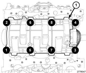
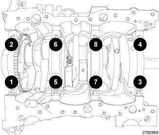
- Remove the eight main bearing cap bolts from the windage tray in the sequence shown in illustration and remove the windage tray (1).CAUTION:
DO NOT use a number stamp or a punch to mark connecting rods or caps, as damage to connecting rods could occur.
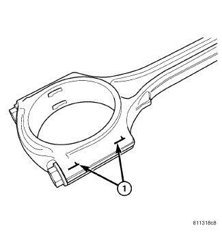
NOTE:Connecting rods and bearing caps are not interchangeable and should be marked before removing to ensure correct reassembly.
- Mark connecting rod and bearing cap positions (1) using a permanent ink marker or scribe tool.CAUTION:
Care must be taken not to damage the fractured rod and cap joint face surfaces, as engine damage may occur.
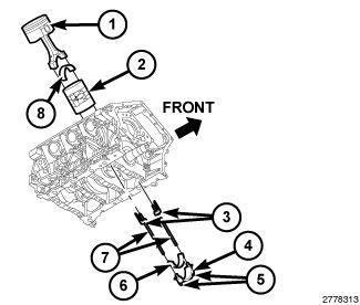
- Remove the connecting rod cap bolts (5) and the connecting rod caps (4). Discard the cap bolts.
- Remove the plastic guide plates (3) from the Guide Pins (special tool #8189, Guide Pins) (7) and install the Guide Pins to the connecting rod.CAUTION:
Care must be taken not to nick crankshaft journals, as engine damage may occur.
- Push the connecting rod and piston into the cylinder until the connecting rod is clear of the crankshaft journal. Remove the guide pins. Repeat this procedure at each cylinder until all of the connecting rods are clear of the crankshaft.
CAUTION:
DO NOT use a number stamp or a punch to mark main bearing caps, as damage to main bearings could occur.
NOTE:If necessary, mark the main bearing cap positions using a permanent ink marker or a scribe tool.
NOTE:Main bearing caps are not interchangeable and are marked to insure correct assembly.
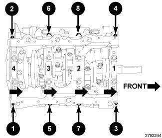
- Remove the main bearing cross bolts in the sequence shown in illustration.
- Remove the eight main bearing cap bolts in the sequence shown in illustration and remove the main bearing caps.CAUTION:
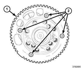
Do not rest the crankshaft on the target wheel (1). Damaged or bent target wheel teeth will destroy the target wheels ability to correctly relay crankshaft position to the crankshaft position sensor.
- Remove the crankshaft from the engine block.
- If required, remove the four bolts (2) and the target wheel (1). Discard the four bolts.