Without HVAC Housing: Removal
To avoid personal injury or death, on vehicles equipped with air bags, disable the supplemental restraint system before attempting any steering wheel, steering column, airbag, occupant classification system, seat belt tensioner, impact sensor, or instrument panel component diagnosis or service. Disconnect and isolate the battery negative (ground) cable, then wait two minutes for the system capacitor to discharge before performing further diagnosis or service. This is the only sure way to disable the supplemental restraint system. Failure to take the proper precautions could result in accidental airbag deployment.
To avoid personal injury or death, never strike or drop the occupant restraint controller, as it can damage the impact sensor or affect its calibration. The occupant restraint controller contains the impact sensor, which enables the system to deploy the supplemental restraints. If an airbag control module is accidentally dropped during service, the module must be scrapped and replaced with a new unit. Failure to observe this warning could result in accidental, incomplete, or improper supplemental restraint deployment.
The Instrument Panel (I/P) can be removed with or without the Heating Ventilation and Air Conditioning (HVAC) housing. The part being serviced will determine if the HVAC housing can stay in the vehicle. This procedure will cover the I/P removal WITHOUT the HVAC housing. unless noted otherwise. Refer to the removal WITH HVAC HOUSING if necessary.
- Before proceeding with the following repair procedure, review all warnings and cautions.
- Remove the steering column. Refer to COLUMN, REMOVAL AND INSTALLATION .
- Remove the floor console. Refer to CONSOLE, FLOOR, REMOVAL AND INSTALLATION .
- Remove the drivers knee airbag. Refer to AIR BAG, KNEE BLOCKER, REMOVAL AND INSTALLATION .
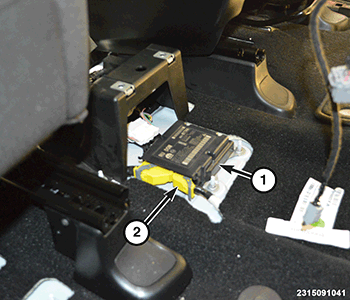
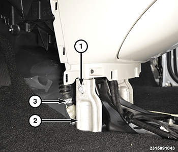
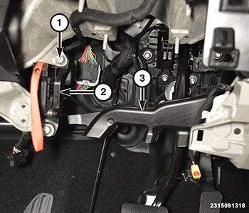
- Remove the two bolts (1) and position the manual park release lever (2) aside.
- Remove the two fasteners and the drivers side floor heat duct (3).
- Release the clips at the front edge of the trim panel (2), then pull rearward and remove.
- Pull outward on the I/P trim panel (1) and remove. Remove the panels from both sides of the I/P.
- Under the passenger side, remove the fasteners and lower the silencer panel. Disconnect the wire harness connector to the lamp and remove.
- Remove the glove box. Refer to GLOVE BOX, INSTRUMENT PANEL, REMOVAL AND INSTALLATION .
- Remove the push fasteners and the soft cover panel in the glove box opening.
- Remove the passenger knee air bag. Refer to AIR BAG, KNEE BLOCKER, REMOVAL AND INSTALLATION .
- Remove the push fasteners and the passenger side floor heat duct.
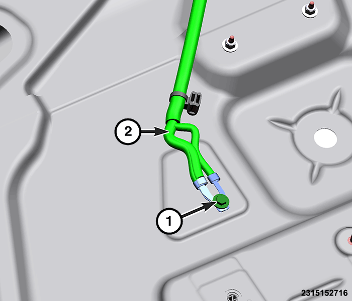
- Disconnect the front wire harness connector (2) from the air bag module (1).
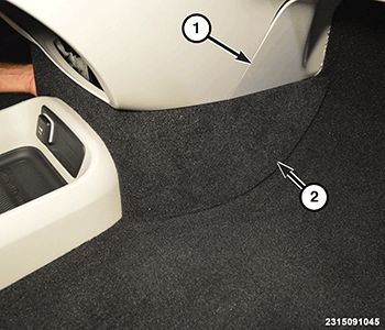
- Pull the passenger side floor carpet (1) back, then remove the nuts (2) and the ground wires. Unclip the wire harness from the body.
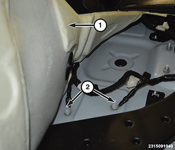
- Pull the driver side floor carpet back, then remove the bolt (1) and the ground wire (2). Unclip the wire harness from the body. If more room is needed to pull back carpet, Remove the driver seat. Refer to SEAT, FRONT, REMOVAL AND INSTALLATION or SEAT, STOW-N-GO, REMOVAL AND INSTALLATION or SEAT, REMOVAL AND INSTALLATION or SEAT, REMOVAL AND INSTALLATION .
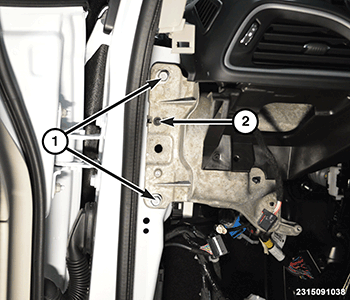
- Remove all bolts (1) and the I/P support bracket (2). Remove both brackets.
- Use a J-nut and bolt (1) to temporary attach one I/P support bracket (3) to the HVAC housing (2), as shown in illustration. This will support the HVAC housing after the I/P is removed.
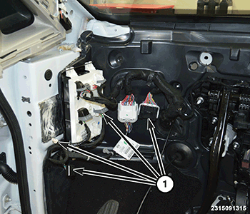
- Under the left side of the I/P disconnect the wire harness connectors (1).NOTE:
This is shown in illustration with the I/P removed for better clarity.
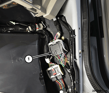
- Under the right side of the I/P disconnect the wire harness connector (1). If equipped with rear entertainment, disconnect the USB connector is this location also.
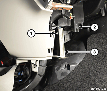
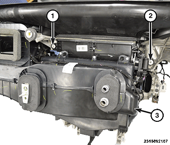
- Reach up high under the I/P on the passenger side and remove the bolt (1) that fastens the HVAC housing (3) to the support structure.NOTE:
This is shown in illustration with the I/P removed for better clarity.
- Reach up under the I/P on the driver side, to the right of the steering column, and remove the bolt (2) that fastens the HVAC housing to the support structure.
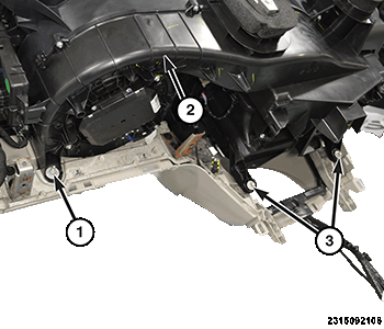
- Remove the nut (1) the passenger side, below the glove box opening, that fastens the HVAC housing (2) to the support structure.NOTE:
This is shown in illustration with the I/P removed for better clarity.
- Remove the two bolts (3), behind the storage bin opening, that fastens the HVAC housing to the support structure.
- Remove the defroster grill. Refer to GRILLE, DEFROSTER, REMOVAL AND INSTALLATION .
- Remove both A-pillar trim panels. Refer to PANEL, A-PILLAR TRIM, REMOVAL AND INSTALLATION .
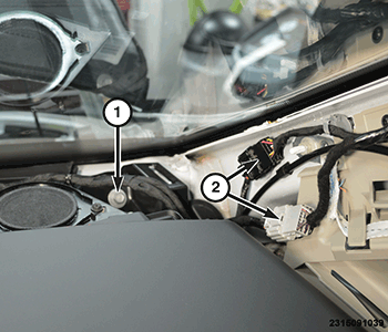
- Disconnect the wire harness connectors (2) at the A-pillar and remove the top I/P bolt (1), on both side of the vehicle.
- Remove the cowl cover panel. Refer to COVER, COWL PANEL, REMOVAL AND INSTALLATION .
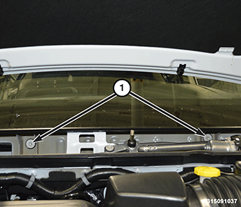
- Remove the two bolts (1) under the cowl cover panel.
- Remove the bolt (2) and discard, this is used for factory installation purposes only. Do this on both sides of the I/P.
- Remove the bolts (1) on both sides of the I/P.
- With the help of an assistant slowly pull the I/P straight rearward and disconnect the wire harness connector to the HVAC housing. Remove it from the vehicle.