Removal And Installation
REMOVAL
- Disconnect and isolate the negative battery cable. If equipped with an Intelligent Battery Sensor (IBS), disconnect the IBS connector first before disconnecting the negative battery cable.
- Raise and support the vehicle. Refer to HOISTING, STANDARD PROCEDURE .
- Remove the belly pan. Refer to BELLY PAN, ENGINE, REMOVAL AND INSTALLATION , BELLY PAN, FRONT, REMOVAL AND INSTALLATION , and/or BELLY PAN, SIDE, REMOVAL AND INSTALLATION .
- Remove the drain plug and allow the fluid to drain from the transmission.
- Install the drain plug and tighten to the proper torque specifications. Refer to TECHNICAL SPECIFICATIONS .
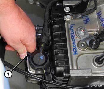
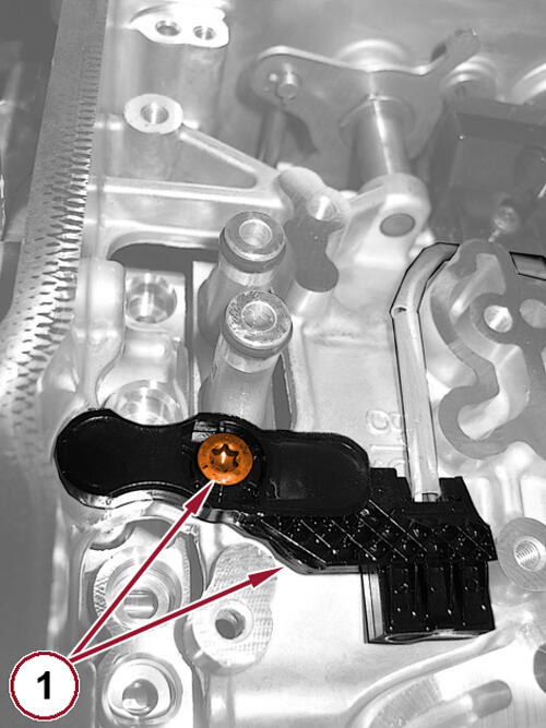
- Rotate the lock lever (1) counterclockwise on the transmission wire harness connector.
- Disengage the transmission wire harness connector from the socket on the transmission pan.
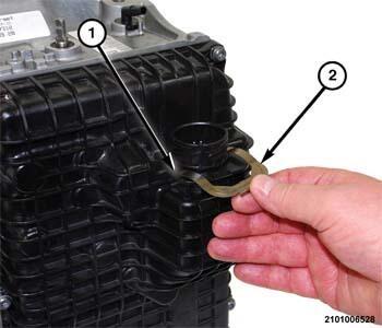
- Using a suitable pry tool, remove the clip (2) holding the wire transmission harness connector socket (1) in the valve body cover.
- Press the transmission wire harness connector socket (1) inside the valve body cover.
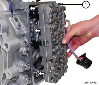
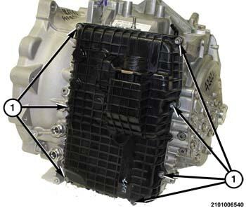
- Remove the bolts (1) holding the valve body cover to the transmission.
- Remove the valve body cover from the transmission housing.
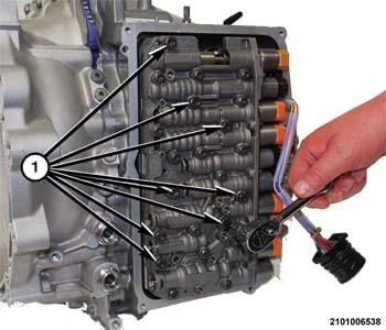
- Remove the valve body bolts (1).NOTE:
The fluid transfer tubes may come out with the valve body.
- Using a suitable prying tool, separate the valve body from the transmission.
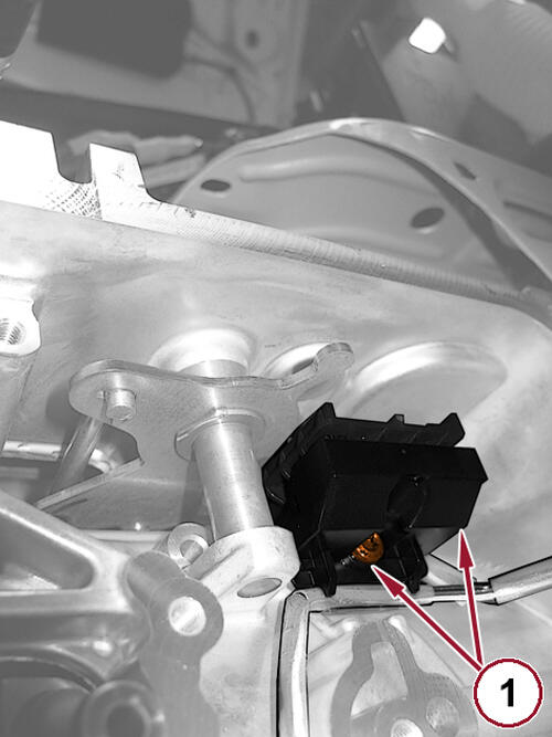
- Remove the Transmission Range Sensor (TRS) mounting screw and separate the TRS from the transmission (1).
- Remove the transmission speed sensor screw and pull the speed sensors from the case (1).
- Remove the valve body with the wire harness from the vehicle.NOTE:
If the valve body is to be reused without disassembling it, store the valve body in a clean area until it is installed.
- If necessary, remove the internal transmission wire harness from the valve body. Refer to HARNESS, INTERNAL WIRE, REMOVAL AND INSTALLATION .
INSTALLATION
NOTE:
Before installing the valve body, replace the O-ring seals on the fluid transfer adapter tubes. Apply a light coating of assembly lube on the O-rings to ease valve body installation.
- If removed, position the internal transmission wire harness into position on the valve body. Refer to HARNESS, INTERNAL WIRE, REMOVAL AND INSTALLATION .
- Clean the mating surfaces between the valve body and the transmission housing with a clean lint-free cloth.
- Install the transmission speed sensors and tighten the screw (1) to the proper specification. Refer to TECHNICAL SPECIFICATIONS .
- Install the Transmission Range Sensor (TRS) and tighten the screw (1) to the proper specification. Refer to TECHNICAL SPECIFICATIONS .
- Turn the valve body (1) over and align the valve body (1) with the fluid transfer adapters.
- Firmly press the valve body inward until the O-rings on the fluid transfer adapters engage into receptacle holes on the valve body.
- Install the valve body bolts and tighten to the proper torque specifications. Refer to TECHNICAL SPECIFICATIONS .
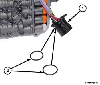
- Install a NEW
O-ring seals (2) on the wire connector socket (1).NOTE:
A light coating of assembly lube can be applied to the O-ring seals (2) to ease installation.
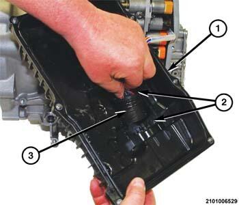
NOTE:If any damage is present to the valve body cover or the valve body cover gasket, replace it with a NEW valve body cover assembly.
- Insert the wire connector socket (3) into the opening on the inside of valve body (1) with the flat side (2) of the socket on the left.
- Place the valve body cover (1) in position on the transmission.
- Press the wire connector socket inward until the retainer clip groove (1) is exposed on the outside of the valve body cover.
- Install the clip (2) to hold the wire connector socket in the valve body cover.
- Install the bolts (1) to hold the valve body cover to the transmission housing and tighten to the proper torque specifications. Refer to TECHNICAL SPECIFICATIONS .
- Engage the transmission wire harness connector into the socket on the valve body cover.
- Rotate the lock lever (1) clockwise onto the transmission wire harness connector.
- Install the belly pan. Refer to BELLY PAN, ENGINE, REMOVAL AND INSTALLATION , BELLY PAN, FRONT, REMOVAL AND INSTALLATION , and/or BELLY PAN, SIDE, REMOVAL AND INSTALLATION .
- Connect the negative battery cable. If equipped with an Intelligent Battery Sensor (IBS), connect the IBS connector to the negative battery cable.
- Fill the transmission. Refer to FLUID AND FILTER, STANDARD PROCEDURE .
- Perform the Valve Body Solenoid Learn procedure if the valve body and/or the Transmission Control Module (TCM) was replaced during a repair.
- Perform Transmission Verification Test-948TE. Refer to TRANSMISSION VERIFICATION TEST - 948TE 9HP48 .