Removal And Installation: Installation
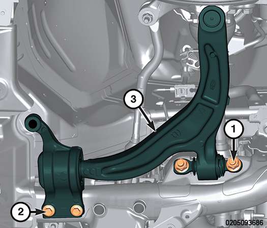
- Position the lower control arm (3) onto the subframe.
- Install two NEW front lower control arm to front subframe mounting bolts (1). Do not tighten at this time.
- Install two NEW
front lower control arm to rear subframe mounting bolts (2). Do not tighten at this time.
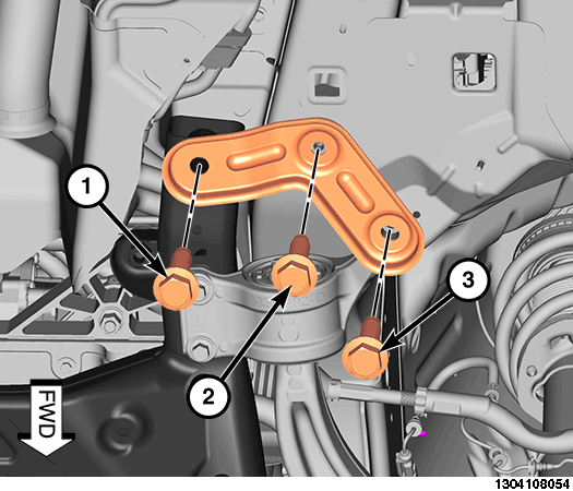
- Position the shear bracket and install NEW
mounting fasteners (1, 2, 3). Do not tighten at this time. WARNING:
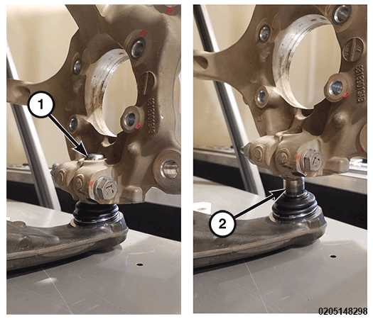
Verify the lower control arm ball joint stud is fully inserted into knuckle before pinch bolt is inserted into knuckle. Only ball joint stud rubber boot should be visible below the knuckle; stud should not be visible. Failure to fully and properly insert ball joint stud could lead to wheel separation and loss of mobility and could result in personal injury or death.
- Position the lower ball joint stud to the steering knuckle and verify it is in the correct position with the ball joint stud visible at the upper portion of the steering knuckle mounting hole (1).NOTE:
If the lower ball joint stud is installed incorrectly with the ball joint stud visible in the lower portion of the steering knuckle mounting hole (2), remove the lower ball joint and reinstall the lower ball joint stud to the steering knuckle and verify the ball joint stud is in the correct position (1).
- Install a NEW ball joint stud pinch bolt (2) and a NEW nut, and tighten to the proper torque specifications. Refer to FRONT, TECHNICAL SPECIFICATIONS .
- Install the front wheelhouse splash shield. Refer to SHIELD, SPLASH, FRONT WHEELHOUSE, REMOVAL AND INSTALLATION .
- Install the side belly pan. Refer to BELLY PAN, SIDE, REMOVAL AND INSTALLATION .
- Install the front belly pan. Refer to BELLY PAN, FRONT, REMOVAL AND INSTALLATION .
- Install the tire and wheel assembly. Refer to REMOVAL AND INSTALLATION .
- Remove the support and lower the vehicle.
- Position the vehicle on an alignment rack. Raise vehicle as necessary to access mounting fasteners.
- Tighten the two front lower control arm to rear subframe mounting bolts to the proper torque specification. Refer to FRONT, TECHNICAL SPECIFICATIONS .
- Tighten the two front lower control arm to front subframe mounting bolts to the proper torque specification. Refer to FRONT, TECHNICAL SPECIFICATIONS .
- Tighten the three shear bracket to subframe mounting bolts to the proper torque specification. Refer to FRONT, TECHNICAL SPECIFICATIONS .