Removal And Installation - All Wheel Drive
REMOVAL
- Disconnect and isolate the negative battery cable. If equipped with an Intelligent Battery Sensor (IBS), disconnect the IBS connector first before disconnecting the negative battery cable.
- Raise and support the vehicle. Refer to HOISTING, STANDARD PROCEDURE .
- Remove the engine belly pans. Refer to BELLY PAN, ENGINE, REMOVAL AND INSTALLATION .
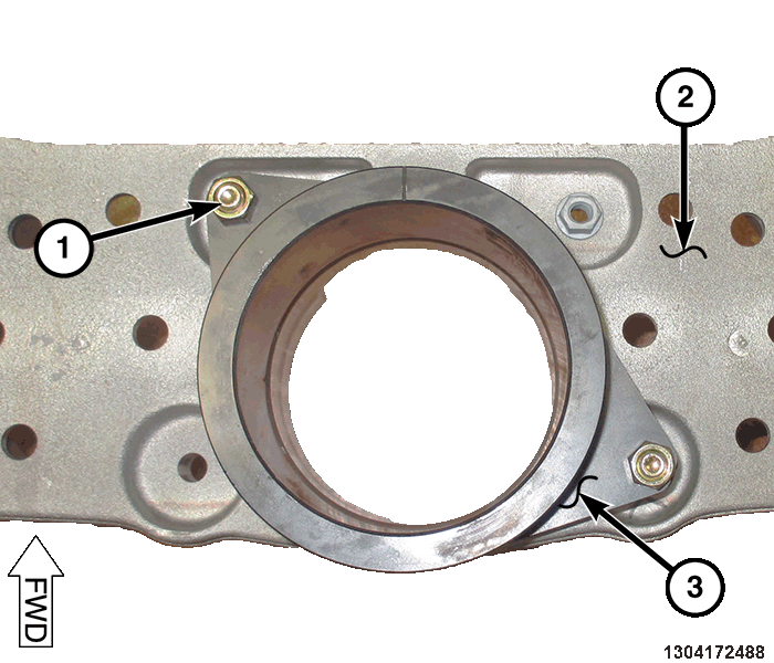
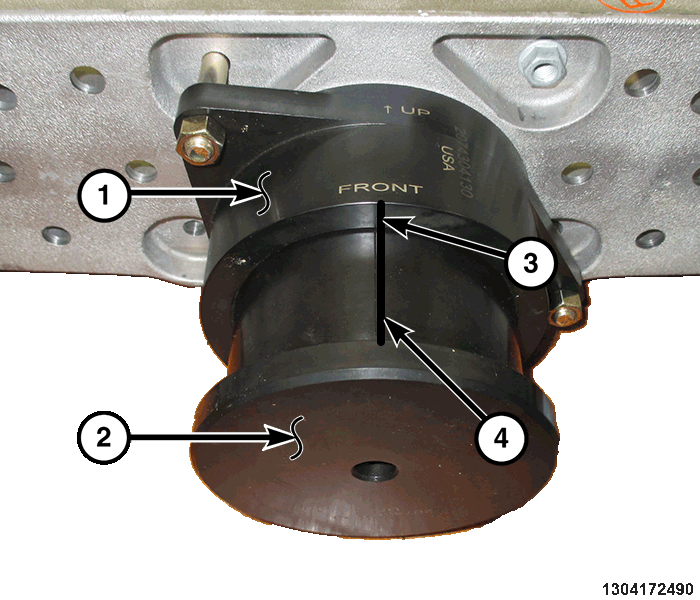
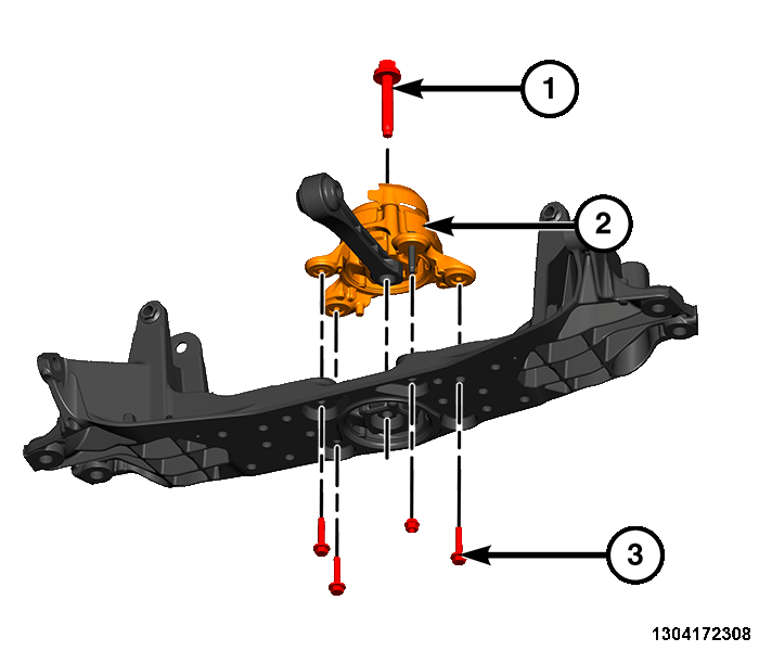
- Remove the fastener (1) attaching the mount (2) to the transmission bracket.
- Remove the fastener (1).
- Remove the lower fasteners (3) and remove the mount (2).NOTE:
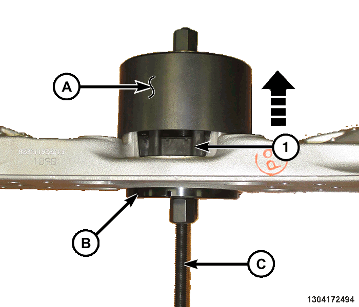
Prior to using special tools, lubricate Pressing Tool (special tool #2026900170, Kit, Pressing Tool) (E) threads to provide ease of use and promote tool longevity.
- Assemble tools over isolator crossmember assembly as shown:
- (special tool #2074302130, Receiver, Lower Torque Strut)
- (special tool #2074303130, Support, Lower Torque Strut-Bottom)
- (special tool #2026900170, Kit, Pressing Tool)
- Tighten Pressing Tool (C), pressing bushing out of crossmember and remove all tools.
INSTALLATION
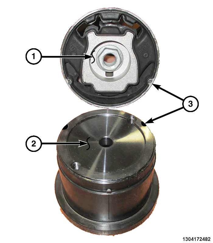
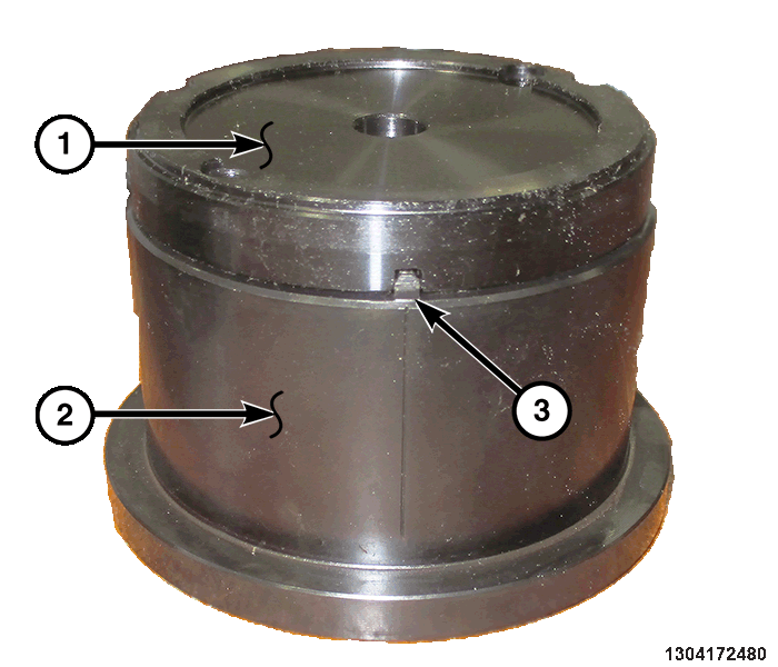
- Assemble the tools together lining up the notch in (special tool #2074303130, Support, Lower Torque Strut-Bottom) with the tab (3) on (special tool #2074301130, Installer, Lower Torque Strut) (2).
- Install the isolator (1) on (special tool #2074303130, Support, Lower Torque Strut-Bottom) (2) lining up tabs to the notches (3) in 2074303130.
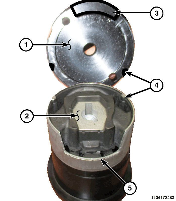
- Install the tool (special tool #2074305130, Support, Lower Torque Strut-Top) (1) on the isolator (2) lining up tabs to the notches (4) in 2074305130 and the large tab (3) in the isolator (2).
- Install the bolts (1) securing the tool (special tool #2074305130, Support, Lower Torque Strut-Top) (2) to the isolator (3) and tool 2074303130 (4).
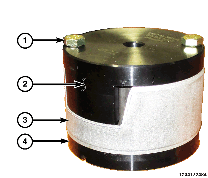
- Install the (special tool #2074304130, Collar, Lower Torque Strut Compression) (3) on the crossmember (2) and install the bolts (1).
- Position the isolator and tool assembly (2) into tool 2074304130 (1) and line up the marks (4) on (special tool #2074301130, Installer, Lower Torque Strut) with the mark on tool 2074304130 (3).NOTE:
A mixture of soap and water may be used to aid installation of the isolator.
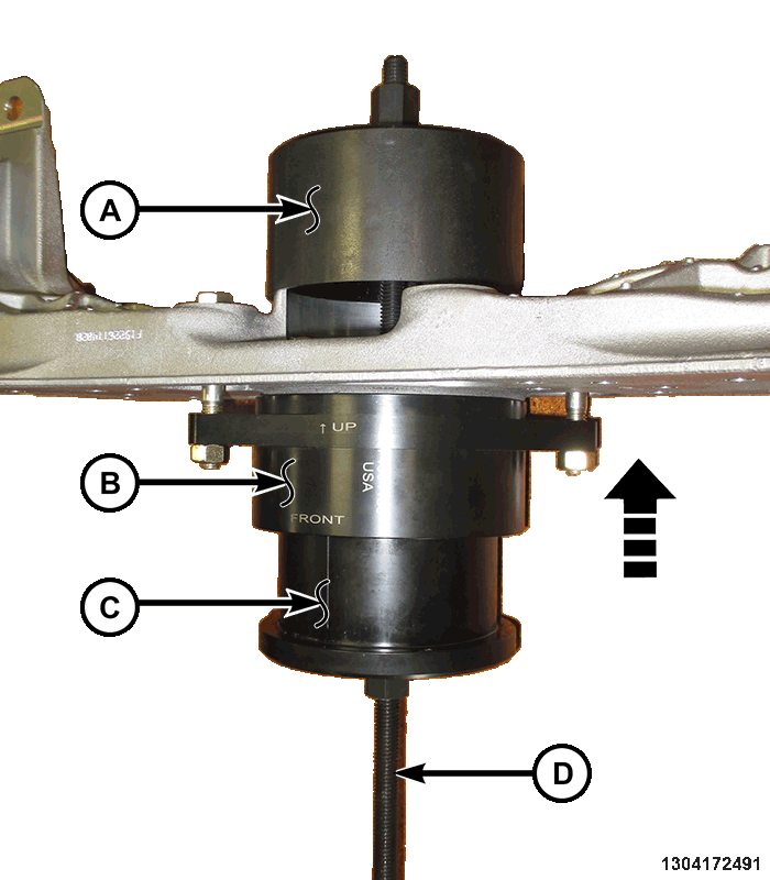
NOTE:Prior to using special tools, lubricate Pressing Tool assembly (special tool #2026900170, Kit, Pressing Tool) (1) threads to provide ease of use and promote tool longevity.
- Assemble tools over isolator crossmember assembly as shown:
- (special tool #2074302130, Receiver, Lower Torque Strut)
- (special tool #2074304130, Collar, Lower Torque Strut Compression)
- (special tool #2074301130, Installer, Lower Torque Strut)
- (special tool #2026900170, Kit, Pressing Tool)
- Tighten the Pressing Tool (special tool #2026900170, Kit, Pressing Tool) (D) screw-drive, pressing isolator into crossmember.
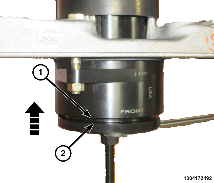
- Install the isolator until the driver tool 2074301130 (2), contacts the surface of the collar tool 2074304130 (1).
- Remove tools.
- Install the mount (2) and install the fasteners (1) and (3) and tighten to the proper torque specifications. Refer to TECHNICAL SPECIFICATIONS
.
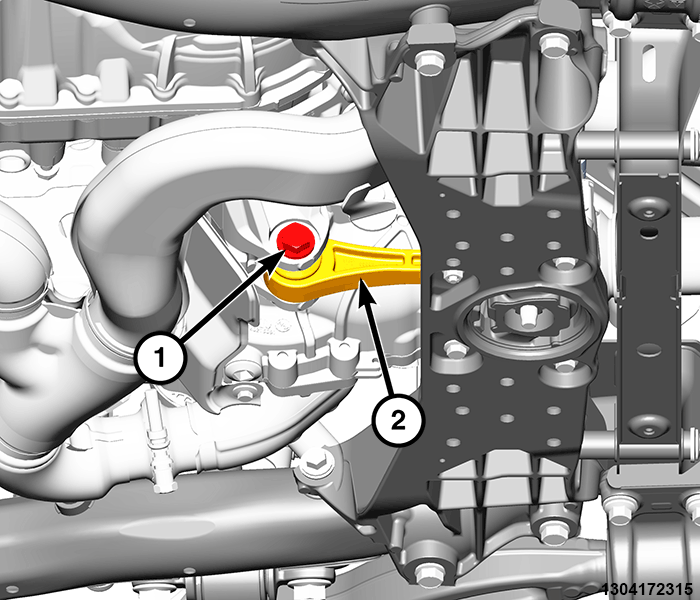
- Position the mount (2) back in the bracket and install the fastener (1).
- Tighten the fastener (1) to the proper torque specification. Refer to TECHNICAL SPECIFICATIONS .
- Install the engine belly pans. Refer to BELLY PAN, ENGINE, REMOVAL AND INSTALLATION .
- Connect the negative battery cable. If equipped with an Intelligent Battery Sensor (IBS), connect the IBS connector.