Removal And Installation: Installation
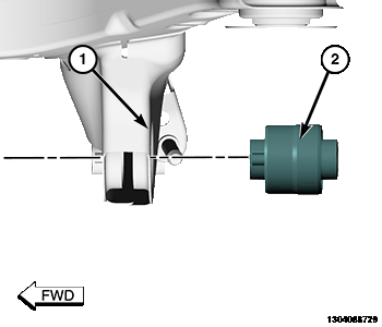
- Position isolator (2) on crossmember isolator bore (1).
- Aligning isolator can flange with reference marks applied during removal.
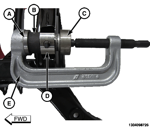
1 - Adapters, Ball Joint Press C-4212-6 2 - Remover/Installer 8836-7 3 - Installer, Bushing Small 2026600170 4 - C-Support, Bushing Small, 2026800170-C 5 - Press, Ball Joint C-4212F - Assemble tools over isolator crossmember assembly as shown:
- (special tool #C-4212-6, Adapters, Ball Joint Press)
- (special tool #8836, Remover/Installer)
- (special tool #2026600170, Installer, Bushing Small)
- (special tool #2026800170-C, Support, Bushing Small)
- (special tool #C-4212F, Press, Ball Joint)
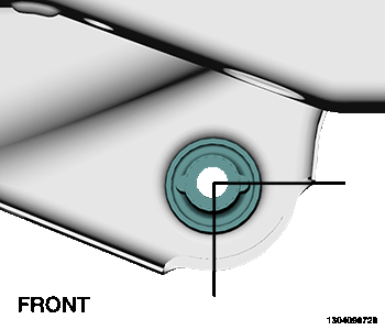
- Tighten Press, Ball Joint (special tool #C-4212F, Press, Ball Joint) (E) screw-drive, pressing isolator into crossmember. Install the isolator until the isolator can flange contacts the surface of the crossmember.
- Remove tools.
- Install the rear crossmember. Refer to CROSSMEMBER, REAR SUSPENSION, REMOVAL AND INSTALLATION .
NOTE:
Prior to using special tools, lubricate Press, Ball Joint (special tool #C-4212F, Press, Ball Joint) (1) threads to provide ease of use and promote tool longevity.
NOTE:
A mixture of soap and water may be used to aid installation of the isolator.