Relative Compression Test - MOPAR Scope
A relative compression test can be performed to help determine if a cylinder has a mechanical issue causing a lack of compression. This can be done by checking the amperage draw by the starter during cranking with an oscilloscope. The amount of peak amperage for each cylinder during a compression stroke will increase or decrease in relation to cylinder compression. If a cylinder has low compression due to a mechanical issue, the amperage draw by the starter will also be lower when that cylinder is on the compression stroke. Follow the steps below to perform a relative compression test with the oscilloscope.
It is important to note when performing this check that the peak amperage can vary from vehicle to vehicle, even with the same engines. There are many variables that can affect this such as the starter motor capacity and age, battery type and capacity, etc. For this reason it is best to compare the cylinders across the engine on the vehicle being tested. Saved readings from another vehicle with the same engine should only be used as a guideline for what is considered normal.
To perform this correctly, the engine must be cranked without trying to start. If the engine is firing cylinders and trying to start it will skew the readings. On some vehicles, the PCM will allow the engine to crank without trying to start if the throttle is held at wide open throttle. Try cranking the engine with the accelerator pedal at wide open throttle to see if the vehicle being tested functions this way. This will allow performing the procedure without having to disable fuel.
- Disable the fuel system so that the engine can crank without starting. Use the wiring information to determine how to disable the fuel pump or fuel injectors. Best method is removing the fuse or relay.
- Start the engine to allow the fuel in the rail and lines to be used up and the engine stalls. It may be necessary to do this a couple of times.
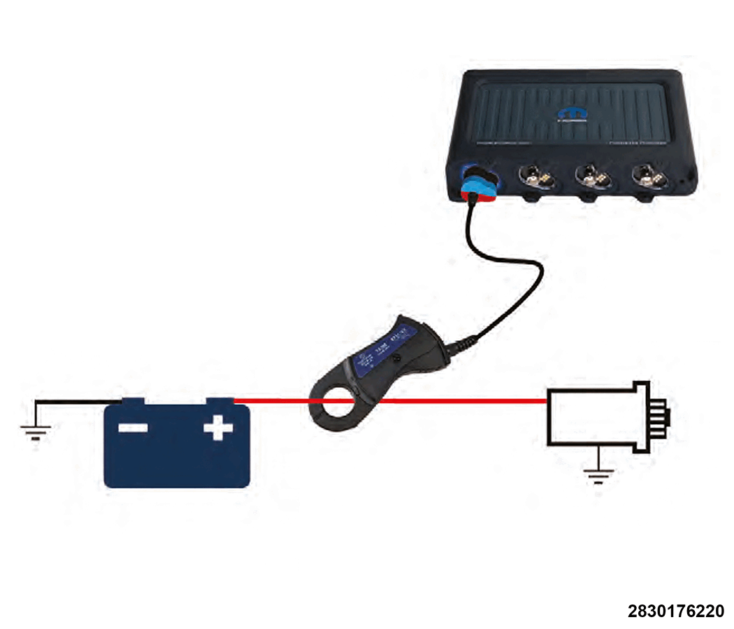
- With the 2000A clamp connected to channel A on the scope, connect the 2000A clamp to the main battery cable that connects between the positive battery post and the starter motor. The clamp can be connected near the battery, the starter or anywhere in between that is accessible.
- Set up the channels and scaling according to the table below:NOTE:
Setting up a trigger will allow auto capturing the data during cranking. If the trigger is not used the scope will need to be manually stopped to capture the data for analyzing. If a trigger is being used, set up the trigger for channel A according to the trigger set-up table below:
OSCILLOSCOPE CHANNEL SET-UP AND SCALING CHANNEL A CHANNEL B CHANNEL C CHANNEL D Scope Lead 2000A clamp Coil on Plug Probe Voltage/Amperage scaling 1kA Auto-scales to 10mA Scope Connection Connect to the battery cable from the battery to the starter motor Place on an ignition coil for reference sync N/A N/A Graph Timing Recommend 500 ms/div TRIGGER SET-UP Mode Trigger Type Direction Threshold Pre-trigger percentage Single Simple Edge Rising 100A 10% - Hold the accelerator pedal at wide open throttle to help prevent the engine from trying to start.
- Crank the engine until the screen fills. If a trigger is not being used, stop the scope when the screen fills or the engine stops cranking.
- Analyze the pulses in the cranking amperage for the cylinders.
When analyzing the amperage draw, do not analyze the initial cranking cycle of the engine. There is always an initial in-rush at starter engagement for the first few cylinders. Analyze the 2nd or 3rd cycle of the engine when the amperage has stabilized.
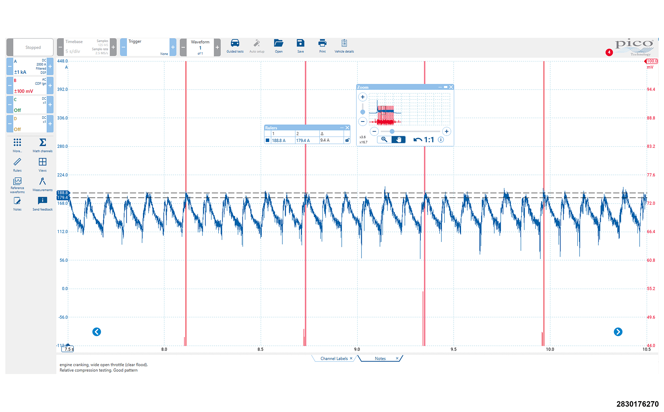
Below is an example of a vehicle with good compression in each cylinder. The amperage peaks will appear to be relatively equal. The red channel is showing ignition coil 1 firing as a sync. A physical compression and leak down test are likely not necessary on this vehicle since the peaks are relatively equal.
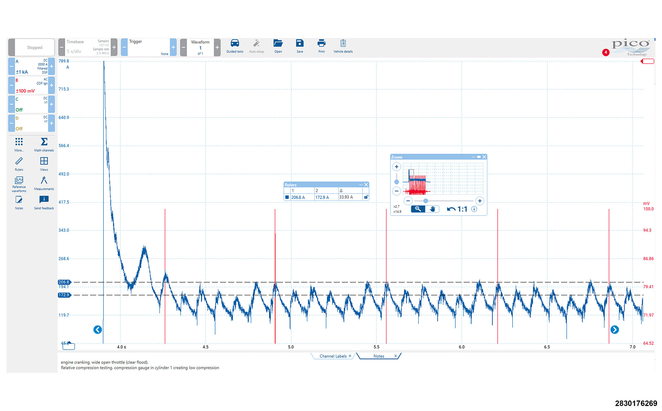
Below is an example of the same vehicle with low compression in cylinder 1. The spark plug was removed and a compression hose was inserted in the cylinder to simulate compression loss. In this example the red channel is showing ignition coil 3 firing as a sync. Using the firing order of 1-2-3-4-5-6 you can see that cylinder 1 is much lower than the cylinders with maximum current draw. In this example cylinder one is lower than all other cylinders. The cylinders before cylinder 1 are closer to the normal readings in the graph above but the cylinders directly after cylinder 1 are slightly higher than the graph above when all cylinders were good. This is normal with a low cylinder. With low compression in a cylinder the starter draw will decrease due to less resistance for the starter to fight on the compression stroke. The lack of compressed air aiding the piston as it travels back down on the combustion stroke will cause an in-rush on the following cylinder(s). If a cylinder has low compression, the difference for the faulty cylinder should be obvious. An actual compression test and cylinder leakage test should be performed to determine the issue.