Removal And Installation: Removal
- Remove the fuel rail pressure sensor. Refer to SENSOR, FUEL RAIL PRESSURE, REMOVAL AND INSTALLATION .
- Drain the cooling system. Refer to STANDARD PROCEDURE .
- Remove the accessory drive belt tensioner. Refer to TENSIONER, BELT, REMOVAL AND INSTALLATION .
- Remove the idler pulleys. Refer to PULLEY, IDLER, REMOVAL AND INSTALLATION .
- Remove the crankshaft vibration damper. Refer to DAMPER, VIBRATION, REMOVAL AND INSTALLATION .
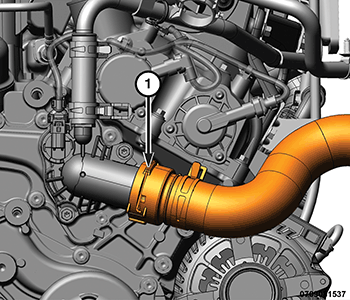
- Remove the upper radiator hose (1) from the thermostat housing.NOTE:
The thermostat housing may be left in place if the timing cover is not being replaced.
- Remove the water pump. Refer to PUMP, WATER, REMOVAL AND INSTALLATION
.
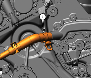
- Remove the heater core supply hose (1) from the coolant crossover.
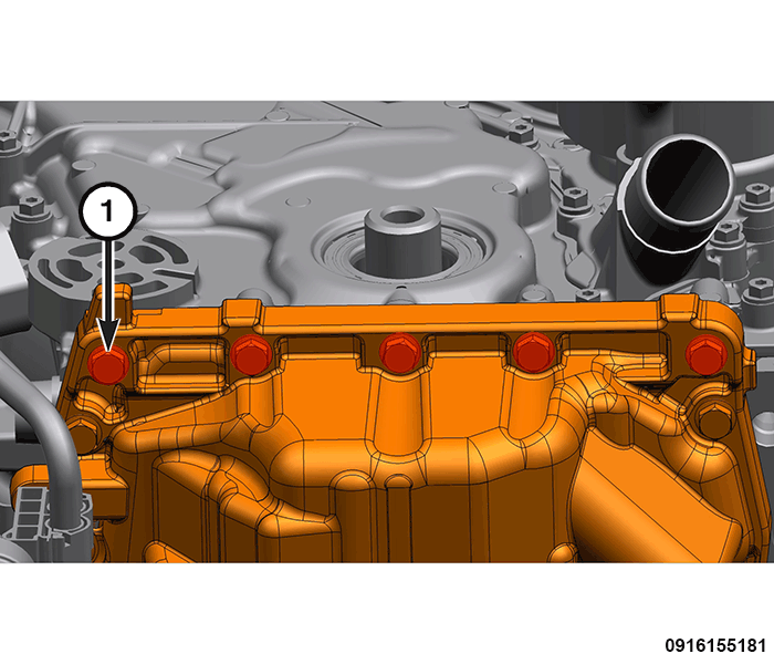
- Remove the five front oil pan to timing cover bolts (1).
- Remove the right and left cylinder head covers. Refer to COVER(S), CYLINDER HEAD, REMOVAL AND INSTALLATION .
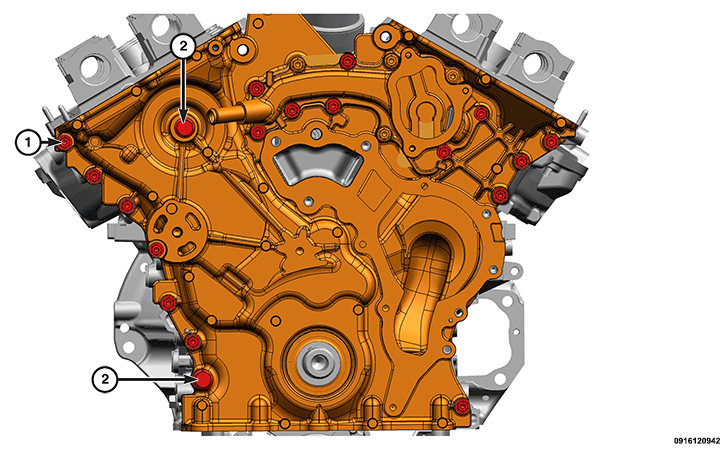
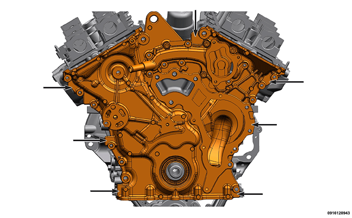
- Remove the M6 bolts (1) and M10 bolts (2) from the timing cover.
- Using the indicated pry points, carefully remove the timing cover.NOTE:
If necessary, the use of a heat gun may assist in removing the timing cover.
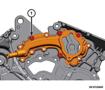
- If required, remove the remaining four M6 bolts (1) and the coolant crossover from the engine timing cover.
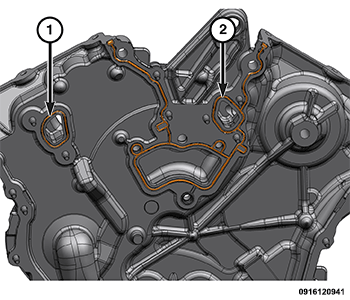
- Remove and discard the coolant crossover gasket (1) and the water pump gasket (2).CAUTION:
Do not use oil based liquids, wire brushes, abrasive wheels or metal scrapers to clean the engine gasket surfaces. Use only isopropyl (rubbing) alcohol, along with plastic or wooden scrapers. Improper gasket surface preparation may result in engine fluid leakage.
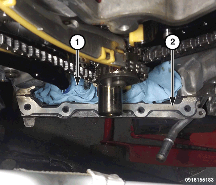
- Insert a shop cloth (1) into the front opening of the oil pan and remove all residual sealant (2) from the oil pan and engine block mating surfaces. Refer to STANDARD PROCEDURE .
- Remove all residual sealant from the timing chain cover and cylinder head mating surfaces. Refer to STANDARD PROCEDURE .NOTE:
Take this opportunity to measure timing chain wear. Refer to VALVE TIMING, STANDARD PROCEDURE .