Theory Of Operation
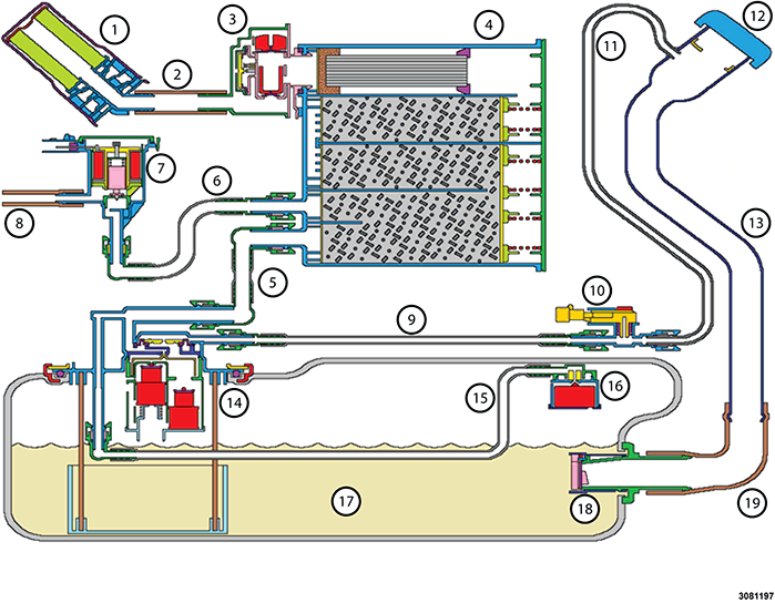
| EVAP SYSTEM COMPONENTS | |
|---|---|
| CALLOUT | DESCRIPTION |
| 1 | Filter - Fresh Air Inlet |
| 2 | Filter Hose (Filter to ESIM) |
| 3 | Evaporative System Integrity Monitor (ESIM) |
| 4 | Evaporative Canister |
| 5 | Canister Tube (Fuel Tank to Canister) |
| 6 | Purge Tube (Purge Solenoid to Canister) |
| 7 | Purge Solenoid |
| 8 | Manifold Hose (Purge Solenoid to Engine Manifold) |
| 9 | Recirculation Tube (Fuel Tank to FTPS) |
| 10 | Fuel Tank Pressure Sensor (FTPS) |
| 11 | Recirculation Tube (metal portion) (FTPS to Fuel Filler Tube) |
| 12 | Gas Cap or Cap-less Refueling Unit (if equipped) |
| 13 | Fuel Filler Tube |
| 14 | Multi-Function Control Valve (MFCV) in the Fuel Delivery Flange |
| 15 | GVV Tube (GVV to MFCV) |
| 16 | Grade Vent Valve (GVV) |
| 17 | Fuel Tank |
| 18 | Inlet Check Valve (ICV) |
| 19 | Hose - Fuel Filler Tube to ICV |
The fuel level is recorded by the Powertrain Control Module (PCM) when the ignition key is turned off, and is compared to the fuel level at the next ignition key on cycle. If the PCM recognizes a 25% increase in fuel level, the Leak Test Monitor is initiated. If the Large leak test fails it is determined that the Fuel Filler Cap is faulty or not installed properly, or the Capless Fuel Filler Assembly flap did not seal properly after fueling. A LOOSE GAS CAP message will be displayed on the cluster to inform the customer.