Diagnostic Test
- CHECK FOR AN ACTIVE CONDITION
- Start the engine and allow it to idle.
- With the scan tool, navigate to data display and monitor the voltage sense to the PCM.
Is the voltage within 0.2 volts of the target charging voltage?
Yes
- Perform the INTERMITTENT CONDITION diagnostic procedure. Refer to INTERMITTENT CONDITION .
No
- Go To 2
- CHECK THE CONDITION OF THE BATTERY NOTE:
Inspect the vehicle for aftermarket accessories that may exceed the Alternator System output.
NOTE:Inspect the fusible link in the charge wire or fuses in the PDC depending on application. If an open fusible link or fuse is found, use the wire diagram/schematic as a guide and inspect the wiring and connectors for damage.
- Use the (special tool #GR8-1220KIT-CHRY, AGM Battery Tester/Charger Station) or equivalent to load test the Battery.
Did the Battery pass or fail?
Passed
- Go To 3
Failed
- Perform the appropriate repair according to the Battery tester.
- Perform the POWERTRAIN VERIFICATION TEST. Refer to POWERTRAIN VERIFICATION TEST .
- Use the (special tool #GR8-1220KIT-CHRY, AGM Battery Tester/Charger Station) or equivalent to load test the Battery.
- CHECK FOR HIGH RESISTANCE IN THE BATTERY POSITIVE CIRCUIT
- Perform a voltage drop test between the Battery Positive (+) Post;
- and the Alternator stud.
- and the PDC B+ terminal.
Is the voltage reading above 0.2 volts for either measurement?
Yes
- Repair the Battery Positive (+) circuit for high resistance.
- Perform the POWERTRAIN VERIFICATION TEST. Refer to POWERTRAIN VERIFICATION TEST .
No
- Go To 4
- Perform a voltage drop test between the Battery Positive (+) Post;
- CHECK FOR HIGH RESISTANCE IN THE BATTERY GROUND CABLE
- Perform a voltage drop test between the Battery Negative (-) post;
- to the engine ground eyelet.
- to the body ground eyelet.
Is the voltage reading above 0.2 volts for either measurement?
Yes
- Repair the Battery ground circuit for high resistance.
- Perform the POWERTRAIN VERIFICATION TEST. Refer to POWERTRAIN VERIFICATION TEST .
No
- Go To 5
- Perform a voltage drop test between the Battery Negative (-) post;
- CHECK THE (A209) FUSED B+ CIRCUIT FOR HIGH RESISTANCE
- Disconnect the PCM C1 harness connector.CAUTION:
Do not probe the PCM harness connectors. Probing the PCM harness connectors will damage the PCM terminals resulting in poor terminal to pin connection. Install the GPEC Diagnostic Adaptor to perform the diagnosis.
- Connect the (special tool #10436, Adapter, GPEC Diagnostic) in line with the PCM C1 harness connector.
- Start the engine and allow it to idle.
- Using a voltmeter, measure the voltage at the (A209) Fused B+ circuit at the GPEC Adaptor.NOTE:
Compare the voltage reading to the voltage at the Alternator output stud. Approximately 2.0 Ohms of resistance in this circuit can drop the voltage by approximately 0.5 volts.
Is the voltage within 0.2 volts of the measurement at the Alternator output stud?
Yes
- Go To 6
No
- Repair the (A209) Fused B+ circuit for high resistance.
- Perform the POWERTRAIN VERIFICATION TEST. Refer to POWERTRAIN VERIFICATION TEST .
- Disconnect the PCM C1 harness connector.
- CHECK THE PCM GROUND CIRCUITS FOR HIGH RESISTANCE BY LOAD TESTING THE CIRCUIT
- Disconnect the PCM harness connectors to isolate the ground circuit.
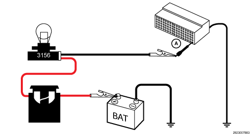
- Connect the positive lead of the load test tool to the positive side of the Battery.
- Connect the negative lead of the load test tool to the ground circuit at the PCM harness connector (A). Note: refer to the diagram below.
- The bulb on the load test tool should be illuminated and bright if there is no resistance in the circuitry.NOTE:
Why load test a circuit? A load test is used to determine if a circuit is capable of carrying the amperage needed to perform properly. The 3156 bulb in the load tool illustrated, is a simple but effective method of testing circuit functionality. A 3156 Bulb has approximately 6.0 Ohms of resistance when the bulb is powered and draws approximately 2.0 amps of current. Read the CIRCUIT LOAD TESTING PROCEDURE for information on building a simple load test tool and for additional load testing information and alternative methods of load testing or voltage drop testing a circuit. Refer to CIRCUIT LOAD TESTING PROCEDURES .
NOTE:A 12-volt test light can be substituted for the load test tool, but only if the test light draws enough current to effectively load test the circuit. Many high impedance test lights draw very little amperage (less than 0.1 amps) and are not reliable to load test a circuit. To perform a proper load test of a circuit, the tool being used should draw more than approximately 0.75 amps.
NOTE:Why perform a Voltage Drop Test? To verify with certainty there is not any resistance in the circuit being tested, perform a simple voltage drop test across the 3156 bulb of the load test tool. To do so perform the following:
- 1. Connect the leads of a DVOM to the alligator clips on the load test tool while the load test tool is connected in series with the circuit.
- 2. Compare the voltage drop across the bulb to the voltage reading across the Battery terminals.
- 3. The voltage dropped across the bulb should be equal to the voltage reading across the Battery terminals if there is no resistance in the circuit being tested.
Example: 2.0 Ohms of resistance in the circuit being tested will cause the voltage measurement across the bulb to be 25% less than when compared to Battery voltage. The reason for this is that the 2.0 Ohms in the circuit makes up 25% of the total circuit resistance of 8.0 Ohms. Read the CIRCUIT LOAD TESTING PROCEDURE for information on building a simple load test tool and for additional load testing information and alternative methods of load testing or voltage drop testing a circuit. Refer to CIRCUIT LOAD TESTING PROCEDURES .
CAUTION:Do not probe the PCM harness connectors. Probing the PCM harness connectors will damage the PCM terminals resulting in poor terminal to pin connection. Install the GPEC Diagnostic Adaptor to perform the diagnosis.
NOTE:IMPORTANT - The GPEC Diagnostic Adaptor can add up to 1.5 Ohms of resistance to the circuit.
- If it is necessary to probe a terminal at a PCM harness connector, connect the (special tool #10436, Adapter, GPEC Diagnostic) to the appropriate PCM harness connector.NOTE:
Compare the brightness of the bulb in the load test tool to that of a direct connection to Battery.
Is the load test bulb illuminated and bright for each ground circuit?
Yes
- Go To 7
No
- Repair the faulty ground circuit for an open or high resistance.
- Perform the POWERTRAIN VERIFICATION TEST. Refer to POWERTRAIN VERIFICATION TEST .
- CHECK RELATED PCM AND COMPONENT CONNECTIONS
- Perform any Service Bulletins that apply.
- Disconnect all PCM harness connectors.
- Disconnect all related in-line harness connections (if equipped).
- Disconnect the related component harness connectors.
- Inspect harness connectors, component connectors, and all male and female terminals for the following conditions:
- Proper connector installation.
- Damaged connector locks.
- Corrosion.
- Other signs of water intrusion.
- Weather seal damage (if equipped).
- Bent terminals.
- Overheating due to a poor connection (terminal may be discolored due to excessive current draw).
- Terminals that have been pushed back into the connector cavity.
- Check for spread terminals and verify proper terminal tension.
Repair any conditions that are found.
- Reconnect all PCM harness connectors. Be certain that all harness connectors are fully seated and the connector locks are fully engaged.
- Reconnect all in-line harness connectors (if equipped). Be certain that all connectors are fully seated and the connector locks are fully engaged.
- Reconnect all related component harness connectors. Be certain that all connectors are fully seated and the connector locks are fully engaged.
- With the scan tool, erase DTCs.
- Test drive or operate the vehicle in accordance with the when monitored and set conditions.
- With the scan tool, read DTCs.
Did the DTC return?
Yes
- Replace the Powertrain Control Module in accordance with the Service information. Refer to MODULE, POWERTRAIN CONTROL (PCM), REMOVAL AND INSTALLATION .
- Perform the POWERTRAIN VERIFICATION TEST. Refer to POWERTRAIN VERIFICATION TEST .
No
- Perform the POWERTRAIN VERIFICATION TEST. Refer to POWERTRAIN VERIFICATION TEST .
- Test complete.