Theory Of Operation
The Camshaft Position (CMP) Sensor circuits consist of a Powertrain Control Module (PCM) supplied 5-Volt reference circuit, low reference circuit, and an output signal circuit. The CMP Sensor detects magnetic flux from the peaks and valleys between the magnets of the tone wheel attached to the camshaft. As each magnet rotates past the CMP Sensor, the resulting change in the magnetic field is used by the sensor electronics to produce a digital output pulse. The sensor returns a digital ON/OFF DC voltage pulse of varying frequency output pulses per Camshaft revolution that represent an image of the camshaft tone wheel. The frequency of the CMP Sensor output depends on the velocity of the camshaft. The PCM decodes the tooth pattern to identify camshaft position. This information is then used to sequence the ignition timing and fuel injection events for the engine. The PCM also uses CMP Sensor output information to determine the camshaft relative position to the Crankshaft, to control the CMP Actuator operation if equipped.
The engine may still start even if either the Crankshaft Position (CKP) Sensor or CMP fails. The PCM eventually sorts out engine position and starts the vehicle on just one of these two inputs. However, there is a slight delay in starting until the PCM can establish sync. A DTC is set and the MIL illuminates if either of the CKP or CMP Sensor signals are not present during engine cranking.
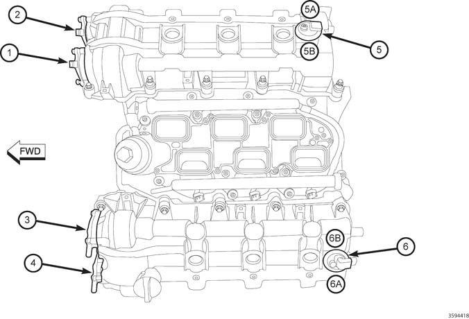
There are four Camshafts and two CMP Sensors. Each CMP Sensor has two CMP Sensor signals that provide feedback indicating the position of each Camshaft on its correlating engine bank (See the illustration and tables below indicating the CMP Sensor, Position Solenoid/Phaser and DTC orientation).
| 3.2L / 3.6L DTCs RELATED TO EACH CAMSHAFT | |||||
|---|---|---|---|---|---|
| CAMSHAFT LOCATIONS | CALLOUT # | RELATED CAM SENSOR DTCS | PHASER/ACTUATOR DTCS | MISALIGNMENT DTCS | COLD START PERFORMANCE DTCS |
| Bank 1 Intake Camshaft | 1 | P0365, P0369 | P000A, P0010 | P0017 | P052A, P052B |
| Bank 1 Exhaust Camshaft | 2 | P0340, P0344 | P000B, P0013 | P0016 | P054A, P054B |
| Bank 2 Intake Camshaft | 3 | P0390, P0394 | P000C, P0020 | P0019 | P052C, P052D |
| Bank 2 Exhaust Camshaft | 4 | P0345, P0349 | P000D, P0023 | P0018 | P054C, P054D |
| 3.2L / 3.6L VVT Component Locations | |||
|---|---|---|---|
| CALLOUT | DESCRIPTION | CALLOUT | DESCRIPTION |
| 1 | CMP Position Solenoid - Bank 1 Position 1 (INTAKE) | 5A | CMP Sensor - Bank 1 Sensor 1 (EXHAUST) |
| 2 | CMP Position Solenoid - Bank 1 Position 2 (EXHAUST) | 5B | CMP Sensor - Bank 1 Sensor 2 (INTAKE) |
| 3 | CMP Position Solenoid - Bank 2 Position 1 (INTAKE) | 6 | Bank 2 Camshaft Sensor |
| 4 | CMP Position Solenoid - Bank 2 Position 2 (EXHAUST) | 6A | CMP Sensor - Bank 2 Sensor 1 (EXHAUST) |
| 5 | Bank 1 Camshaft Sensor | 6B | CMP Sensor - Bank 2 Sensor 2 (INTAKE) |