Theory Of Operation
The Variable Valve Timing (VVT) system continuously varies the Camshaft target position based on the engine operating parameters. Based on these parameters, the Powertrain Control Module (PCM) calculates or models the optimum Camshaft position. The Camshaft angular position is varied by the oil control valve. The VVT solenoid pushes on a plunger (spring loaded spool valve) in the center of the Oil Control Valve (OCV) which directs oil pressure to the hydraulic actuator (Phaser) on the Camshaft Sprocket to change the Camshaft position relative to the Crankshaft position. The VVT Solenoid, acting on the Oil Control Valve and Phaser, is controlled by the PCM. The Camshaft Position (CMP) Sensor is used to monitor the position of the Camshaft.
For the PCM to run this diagnostic the CMP Sensor and CKP Sensor signals must be locked with no sensor faults present. A missing or erratic CMP or CKP signal cannot cause a slow response fault to set. Replacing either sensor will not fix the vehicle.
The PCM performs the typical diagnostic checks on the control circuits. During operation of the system the PCM also performs a Target Error and a Slow Response diagnostic check of the Camshaft phasing since these conditions could potentially increase tailpipe emissions. The diagnostic is primarily performed by comparing the actual Camshaft position to that of a calculated model for the Camshaft position. This diagnostic is continuous once the enable conditions are met. The Slow Response and Target Error conditions are not performed simultaneously.
- The Target Error diagnostic evaluates the actual Camshaft position versus the modeled position when the Camshaft is in a relatively stable position. The difference between the two is considered to be the amount of "error". If the error amount is greater than a calibrated threshold, it is considered failing.
- The Slow Response diagnostic is only performed when the modeled Camshaft position is moving (phasing) in a particular direction, advancing or retarding. The modeled Camshaft phasing position is created to match only the worst possible case of a passing Camshaft position. If the actual Camshaft phasing operates slower than the model by a calibrated threshold, it is considered failing.
If either of these diagnostics fail, the Camshaft Position Slow Response fault will set. Any oil pressure issues, VVT Solenoid or Oil Pump Solenoid Control circuit faults should be diagnosed before diagnosing a Camshaft Position Slow Response fault.
On occasion a small piece of debris or metal chip can get lodged in the OCV causing the spool valve to stick. The contamination can either dislodge on it's own or when the PCM is running a cleaning procedure on the OCV causing an intermittent fault condition for a Camshaft Position Slow Response that is no longer present.
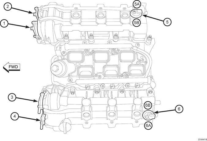
There are four Camshafts and two CMP Sensors. Each CMP Sensor has two CMP Sensor signals that provide feedback indicating the position of each Camshaft on its correlating engine bank (See the illustration and table below indicating the specific orientation of the DTCs to the Camshafts).
| 3.2L/3.6L DTCs RELATED TO EACH CAMSHAFT | ||||
|---|---|---|---|---|
| CAMSHAFT POSITION | RELATED CAM SENSOR DTCS | PHASER/ACTUATOR DTCS | MISALIGNMENT DTCS | COLD START PERF DTCS |
| (1) Bank 1 Intake Camshaft | P0365, P0369 | P000A, P0010 | P0017 | P052A, P052B |
| (2) Bank 1 Exhaust Camshaft | P0340, P0344 | P000B, P0013 | P0016 | P054A, P054B |
| (3) Bank 2 Intake Camshaft | P0390, P0394 | P000C, P0020 | P0019 | P052C, P052D |
| (4) Bank 2 Exhaust Camshaft | P0345, P0349 | P000D, P0023 | P0018 | P054C, P054D |