Theory Of Operation
For proper engine control and combustion stability the Camshaft (CMP) and Crankshaft (CKP) positions must be aligned and known so that fuel injection and spark timing can be introduced at the intended Piston and Intake/Exhaust Valve positions. During vehicle manufacturing, at end of line, or if a Cam/Crank Relearn is performed, the system learns the difference between the Camshaft and Crankshaft position in terms of engine degrees and stores it in the EEPROM. During every following driving cycle, the Powertrain Control Module (PCM) uses this value to compare.
Within a driving cycle, once the CMP position and CKP position are known and verified they are considered "locked." This diagnostic will only run when both sensor signals are in the "locked" state. Engine position is constantly tracked as the CMP Sensor and CKP Sensor signals are monitored by the PCM. An engine rotating at a constant speed would produce engine signals that match the nominal pattern exactly. With engine acceleration and deceleration the engine signals are compressed or stretched in time relative to nominal timing. The PCM takes into account and adjusts for any acceleration/deceleration rates that are in effect.
The misalignment fault accounts for angular deviation between the CMP Sensor and CKP Sensor signals due to miss builds, chain stretch, or skipped tooth. This fault results from the difference between the positions as indicated by the CMP Sensor and CKP Sensor signals. The result is only valid if both positions are "locked".
A missing or erratic CMP or CKP signal cannot cause a Cam/Crank Misalignment fault to set. Replacing either sensor will not fix the vehicle.
On occasion a small piece of debris or metal chip can get lodged in the OCV causing the spool valve to stick. The contamination can either dislodge on it's own or when the PCM is running a cleaning procedure on the OCV causing an intermittent fault condition for a Camshaft/Crankshaft Misalignment that is no longer present.
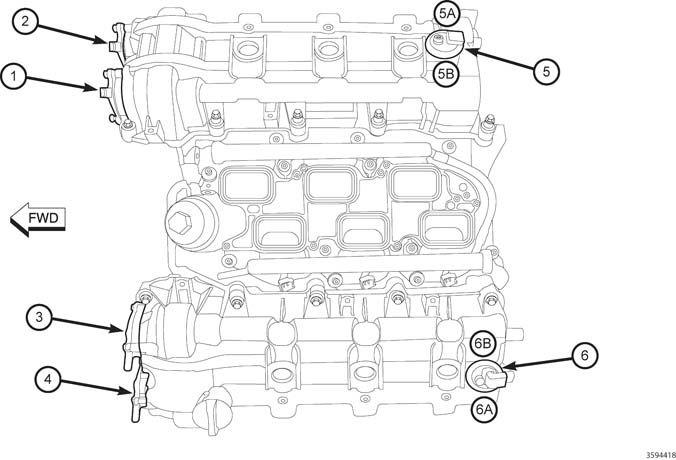
There are four Camshafts and two CMP Sensors. Each CMP Sensor has two CMP Sensor signals that provide feedback indicating the position of each Camshaft on its correlating engine bank (See the illustration and table below indicating the specific orientation of the DTCs to the Camshafts).
| 3.2L/3.6L DTCs RELATED TO EACH CAMSHAFT | |||||
|---|---|---|---|---|---|
| CAMSHAFT LOCATIONS | CALLOUT # | RELATED CAM SENSOR DTCS | PHASER/ACTUATOR DTCS | MISALIGNMENT DTCS | COLD START PERF DTCS |
| Bank 1 Intake Camshaft | 1 | P0365, P0369 | P000A, P0010 | P0017 | P052A, P052B |
| Bank 1 Exhaust Camshaft | 2 | P0340, P0344 | P000B, P0013 | P0016 | P054A, P054B |
| Bank 2 Intake Camshaft | 3 | P0390, P0394 | P000C, P0020 | P0019 | P052C, P052D |
| Bank 2 Exhaust Camshaft | 4 | P0345, P0349 | P000D, P0023 | P0018 | P054C, P054D |