Diagnostic Test
- VERIFY DIAGNOSTIC TROUBLE CODE (DTC) IS STORED NOTE:
Stored faults may indicate a customer perceived intermittent condition.
NOTE:Make sure the battery voltage is between 10 and 16 volts before proceeding.
- Turn the ignition on.
- With the scan tool, read stored DTCs and record on the repair order.
Is this DTC stored?
Yes
- Go To 2
No
- Go to and perform the appropriate diagnostic procedure.
- CHECK THE ENVIRONMENTAL DATA
- With the scan tool, read the loss of communication environmental data.
Does the loss of communication environmental odometer data match up to any of the previous service procedures listed in the possible causes or are there any stored CAN C hardware electrical, battery, ignition voltage, VIN missing/mismatch, or BCM configuration DTCs present with matching environmental data?
Yes
- These DTCs may have been the result of other service procedures performed. Clear the DTCs.
- Perform the BODY VERIFICATION TEST. Refer to BODY VERIFICATION TEST .
No
- Go To 3
- With the scan tool, read the loss of communication environmental data.
- VERIFY INTERMITTENT LOST COMMUNICATION DTC - WIRING CONCERNS
- With the scan tool, read all DTCs.
Is there more than one ECU with stored DTCs "Logged Against" the module and one or more lost communication DTCs stored in the sending module?
Yes
- Verify if the vehicle was recently in for this type of service. Otherwise, visually inspect the related wiring harness for chafed, pierced, pinched, and partially broken wires and the wiring harness connectors for broken, bent, pushed out, and corroded terminals. Repair as necessary.
No
- Go To 4
- With the scan tool, read all DTCs.
- VERIFY INTERMITTENT LOST COMMUNICATION DTC - SENDING MODULE
- With the scan tool, read all DTCs.
Is there more than one ECU with stored DTCs "Logged Against" the module and NO lost communication DTCs stored in the sending module?
Yes
- Check for a Service Bulletin related to this sending module.
No
- Go To 5
- With the scan tool, read all DTCs.
- VERIFY INTERMITTENT LOST COMMUNICATION DTC - REPORTING MODULE
- With the scan tool, read all DTCs.
Is there ONLY ONE ECU with stored DTCs "Logged Against" the module?
Yes
- Check for a Service Bulletin related to the module that set this DTC.
No
- Go To 6
- With the scan tool, read all DTCs.
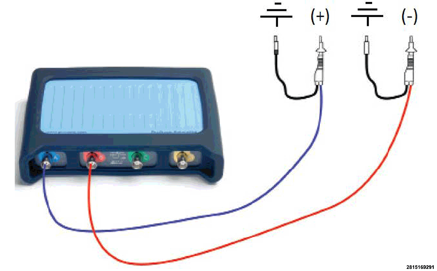
- CHECK THE CAN BUS COMMUNICATION WITH THE MOPAR SCOPE NOTE:
Some vehicles can have multiple CAN connections within a connector, make sure that you are testing the same CAN for both circuits.
Connect the black pin for each test lead to Chassis ground. Connect the blue lead to CAN (+) and the red lead to CAN (-) for the circuits to be tested.
- Start the Mopar Scope.
- Once the Mopar Scope is running, select Guided Tests .
- Select Communications .
- Select CAN L&H .
- Select CAN bus testing / diagnostics .
- Select Load settings file .
- Turn the ignition on.NOTE:
When connected to the vehicle harness correctly, the LEDs on the breakout box will light up to indicate that there is activity on the bus.
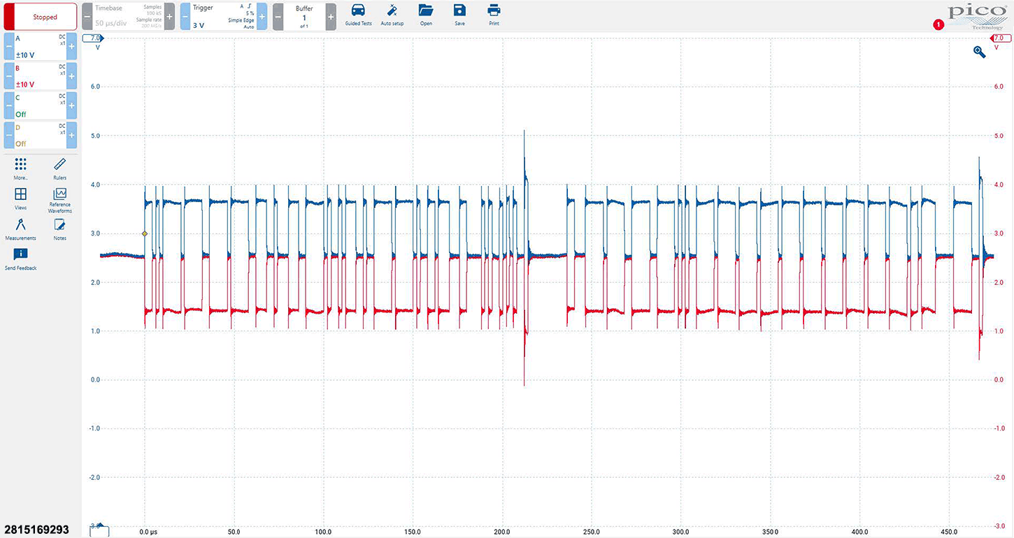
- A waveform should appear.
The image below is of a normal CAN bus waveform using the Mopar Scope. The waveform should reveal that data is being exchanged continuously along the CAN bus and the peak voltages are correct.
DESCRIPTION MEASUREMENT CHANNEL A 10 volts CHANNEL B 10 volts TIME BASE 50 μs/div [microseconds / division control] ZOOM / VIEW X1 - HORIZONTAL & VERTICAL With the Mopar Scope running, use the wiring diagrams as a guide to trace the circuits and look for any in-line connectors where the fault could occur intermittently by wiggling ALL related wire harness and connectors.
NOTE:A reporting ECU sets DTCs against a Sending ECU.
Did the Mopar Scope show the CAN bus waveform fault?
Yes
- Check for related Technical Service Bulletins (TSB's).
- Repair any conditions that are found.
- For intermittent communication issues, or if multiple communication related DTCs are set in other Electronic Control Modules (ECUs), check the suspected ECU power and ground circuits, including at the body sheet-metal, for loose or poor connections. Performing a load test on these circuits will verify the circuit is capable of carrying the amperage needed to perform properly, along with confirming that excessive resistance does not exist in the circuit(s) being tested. For additional information on CIRCUIT LOAD TESTING PROCEDURES. Refer to STANDARD PROCEDURE .
- If there is a history of this DTC setting multiple times, replace the reporting ECU in accordance with the Service Information.
- Perform the appropriate VERIFICATION TEST. If a VERIFICATION TEST is not available for an ECU, perform the BCM VERIFICATION TEST. Refer to BODY VERIFICATION TEST .
- If there is a history of this DTC setting multiple times, replace the sending ECU in accordance with the Service Information.
- Perform the appropriate VERIFICATION TEST. If a VERIFICATION TEST is not available for an ECU, perform the BCM VERIFICATION TEST. Refer to BODY VERIFICATION TEST .