Diagnostic Test
TECH TIPS:
- Note that the RDM will only have a smart actuator on the two speed systems.
- It is important to remember that the Rear Drive Module (RDM) clutch must engage and bring the propeller shaft up to speed to match the front axle speed for the PTU to engage smoothly and properly when the vehicle is moving. Issues with the hydraulic pump or worn clutches in the RDM can cause poor PTU engagement causing grinding or delayed engagement causing performance faults in the PTU. Any RDM faults or issues should be diagnosed before diagnosing any PTU faults. RDM overtemp faults can be an indicator of a slipping torque transfer clutch assembly.
- If the DTCM is replaced, the Restore Vehicle Configuration procedure must be performed for the system to operate correctly and not set a configuration mismatch DTC. A configuration mismatch can also set if an incorrect smart actuator is installed.
OVERTEMP DIAGNOSTICS FOR THE PTU SMART ACTUATOR (C1495-98): If there are any other system faults in the PTU or RDM systems, diagnose the other faults with the PTU or RDM systems. Typically, an issue with one of the assemblies that is causing improper shifting and overworking the system will set other system performance DTCs. If the system only has an overtemp fault, this condition may not require a repair action to correct since the system can set an overtemp fault during extreme use. Verify the following items before clearing an overtemp fault and returning to the customer.
- Verify the fluid level and type are correct.
- If the fluid is low or appears to be incorrect, top off or change the fluid and retest the system for proper operation. If the fluid is low, perform a visual inspection and repair any leaks found.
- If the fluid is full and appears ok, continue testing is step 2.
- Test drive the vehicle in Auto mode and listen for any grinding or clashing when the PTU is switching modes. This could occur if the propeller shaft is not coming up to speed due to an issue with the RDM clutch, or mechanical issues in the PTU (worn or damaged collar or shaft splines).
- If the system appears to be operating and shifting normally, no abnormal noises are heard and the fault does not return, no repair is likely needed, Return the vehicle to the customer and advise that the issue may have been caused by overworking the system.
- If the system appears to be operating and shifting normally, but the fault returns, continue to step 3.
- If the system is not shifting properly, or is clashing when engaging AWD, verify that the RDM clutches are engaging and bringing the propeller shaft to speed during engagement. Slipping RDM clutches can cause an eventual overheat condition in the RDM. If the RDM is operating normally, replace the PTU in accordance with the service information. If the RDM is not operating properly, replace the RDM in accordance with the service information
- If one of the smart actuator overtemp faults is present, replace the smart actuator in accordance with the service information. If the C1472-92 fault was present and one or both of the clutch RDM overtemp faults returned, replace the RDM in accordance with the service information.
COMPLETE CIRCUIT AND PERFORMANCE DIAGNOSTICS FOR THE PTU SMART ACTUATOR (C1495-16, C1495-17, C1494-92, C1496-92, C14A7-97):
- Using the wiring information as a guide, check the fuse that supplies the Fused B+ circuit for PTU Smart Actuator. Verify the fuse is not open and has a good connection with the terminals in the PDC.
- If the fuse is good, continue testing in step 2.
- If the fuse is open, check the Fused B+ circuit and for a short to ground before replacing the fuse.
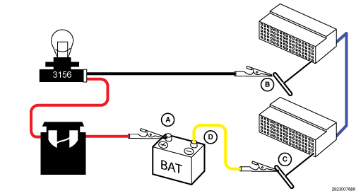
- Disconnect the smart actuator harness connector. Load test the Fused B+ and ground circuits at the actuator harness connector. With the ignition on, connect one lead of the load test tool to the Fused B+ circuit and the other lead of the load test tool to the ground circuit. The load test bulb should be bright if both circuits are good. To verify that there is no resistance in the circuits being tested, perform a simple voltage drop test across the 3156 bulb of the load test tool. The voltage drop across the bulb should be equal to the voltage reading across the battery terminals if there is no resistance in either circuit.NOTE:
Read the CIRCUIT LOAD TESTING PROCEDURE for information on building the load test tool, additional load testing information and alternative methods of load testing or voltage drop testing a circuit. Refer to STANDARD PROCEDURE .
- If the circuits fail the load test, remove the lead connected to the ground circuit and connect it to a good chassis ground. Check the voltage drop across the 3156 bulb of the load test tool again. If the voltage drop is still less than battery voltage, repair the Fused B+ circuit for an open or high resistance. If the voltage drop is now equal to battery voltage, repair the ground circuit for an open or high resistance.
- If the Fused B+ and ground circuits check good, continue to step 3.
- Verify the fluid level and type are correct.
- If the fluid is low or appears to be incorrect, top off or change the fluid and retest the system for proper operation.
- If the fluid appears ok, continue testing is step 4.
- Remove the smart actuator from the PTU. Inspect the shift fork and shaft on the actuator for damage (excessive wear, broken or bent). Also inspect the inside of PTU for signs of damage such as metal particles, damaged splines, collars, gears, etc.
- If there does not appear to be any damage inside the assembly, and the shift fork and shaft appear to be ok, replace the smart actuator in accordance with the service information. Retest the system for proper operation. If the fault returns, replace the Power Transfer Unit.
- If there appears to be damage or metal particles inside the assembly, or the shift fork and shaft appear to damaged or broken, replace the Power Transfer Unit in accordance with the service information.
IMPORTANT DTC DESCRIPTION INFORMATION: The DTC descriptions with T-CASE MOTOR and T-CASE CLUTCH PRESSOR SENSOR called out are used for the REAR DRIVE MODULE HYDRAULIC PUMP and PRESSURE SENSOR on this system.
TECH TIPS:
- If the DTCM is replaced, the Restore Vehicle Configuration procedure must be performed for the system to operate correctly and not set a configuration mismatch DTC. A configuration mismatch can also set if an incorrect smart actuator is installed.
COMPLETE SYSTEM DIAGNOSTICS (C1415-92, C1440-64): The pressure reading, hydraulic pump control circuit voltages and pump current values can be monitored in the scan tool data for most applications. The hydraulic pump and sensor are referred to as the DTCM ECC Motor and Pressure Sensor in the scan tool data reads. The RDM Motor data reads refer to the RDM smart actuator shift fork (if equipped).
- Perform an initial check of the system with the ignition on and the pump motor commanded off to verify the sensor signal and DTCM operation. Turn the ignition on, vehicle in PARK. Using the scan tool, monitor the pressure sensor reading, hydraulic pump duty cycle and current data for 5 minutes. A lab scope can be used to monitor the current draw on the pump motor circuits as well as using the scan tool. There should be no current flow and the pressure sensor signal data should show less than 5.0 kPa.
- DTCM Current monitoring failure checks: There are two ways the DTCM can fail and cause a fault. If the scan tool is showing a negative current draw reading, or if there is current flow above 0.5 amps with the pump commanded off (0% duty cycle), the internal DTCM current sensor is faulty. If either condition is present, replace the DTCM in accordance with the service information.
- Pressure sensor check:
If the ECC Pressure Sensor reading is above 5.0kPa (0.73psi) with 0% duty cycle and no current flow, either the pressure sensor is drifted out of range or there is resistance in the pressure sensor circuitry.
- Isolate and check the pressure sensor circuits for the high resistance, above 3.0 Ohms. If there is high resistance in one or more of the circuits, repair the resistance in the circuit. If all circuits test good, replace the pressure sensor and retest.
- If the initial readings are correct, continue testing in step 2.
- Turn the ignition on with the vehicle in PARK. Monitor the ECC Motor A and Motor B voltage on the scan tool. If not available on the scan tool, using a DVOM, back probe and check the voltage on motor B control and motor A control circuits. Both voltage readings should be approximately 2.8 volts with the pump not energized.
- If both circuits measure approximately 2.8 volts, continue testing is step 3.
- If both circuits do not measure approximately 2.8 volts with the pump commanded off, perform the HYDRAULIC PUMP CIRCUIT FAULT SYSTEM DIAGNOSTICS information below to check for pump circuit issues.
- Check the hydraulic pump functionality. NOTE: This test step is being performed assuming that the hydraulic pump control circuits were good, with no opens or shorts.
Using the scan tool, monitor the hydraulic pump current draw, hydraulic pump duty cycle and pressure sensor readings. Start the engine and put the vehicle in DRIVE with the brake pedal pressed, (vehicle stopped). The hydraulic pump should now be commanded on. With the duty cycle at the lower range (approximately 8 - 12%) there should be some current flow (approximately 1 - 2 amps) and the pressure sensor should now show some pressure. Test drive the vehicle and operate the vehicle under moderate to heavy acceleration while monitoring the readings. As the duty cycle increases the amperage draw should increase significantly (to as much as 10 - 15 amps) and the pressure reading should increase accordingly.
- If the motor current and pressure sensor reading are low when the duty cycle is high it could indicate low RDM hydraulic fluid in the system or a faulty pump motor. Continue testing in step 4.
- An excessively high current draw with low pressure could indicate a blocked pump, an internal short across the coil windings or the control circuits are shorted together. Continue testing in step 5.
- If the motor current appears to be increasing with the duty cycle, but the pressure sensor is not increasing it indicates that the sensor is likely stuck. Replace the pressure sensor in accordance with the service information and retest.
- The RDM assembly is filled with one fluid to lubricate the internal components and a separate hydraulic fluid to operate the clutches. The RDM hydraulic fluid is a fill for life fluid. The level should be full unless there is a leak at the hydraulic pump assembly or pressure sensor.
- If the RDM is leaking hydraulic fluid from the pump or sensor, repair the leak and verify that the RDM hydraulic fluid is filled to the proper level and bled properly. Refer to the service information for the proper procedure to check the hydraulic fluid level and bleed the system. Retest system operation.
- If the system is not leaking, replace the hydraulic pump assembly in accordance with the service information. Refer to the service information for the proper procedure to check the hydraulic fluid level and bleed the system. Retest system operation.
- Turn the ignition off. Disconnect the hydraulic pump and DTCM harness connectors to isolate the circuits. Check for continuity between the motor A control circuit and motor B control circuit.
- If there is continuity present, repair the shorts between the circuits.
- If no continuity is present, replace the hydraulic pump in accordance with the service information. Refer to the service information for the proper procedure to check the hydraulic fluid level and bleed the system. Retest system operation.
HYDRAULIC PUMP CIRCUIT FAULT SYSTEM DIAGNOSTICS (C140B-11, C140B-12, C140B-13):
- Turn the ignition on and the vehicle in PARK. The hydraulic pump should not be on. This can be verified by checking the pump current draw and pressure reading on the scan tool. Monitor the ECC Motor A and Motor B voltage on the scan tool. If not available on the scan tool, using a DVOM, back probe and check the voltage on motor B control and motor A control circuits. Both circuits should have approximately 2.8 volts with the pump motor off.
- If both circuits are measuring approximately 2.8 volts, continue testing in step 2.
- If the motor A control circuit is measuring 3.6 volts and motor B control circuit is measuring 0 volts, it would indicate that one of the circuits is open. Continue testing in step 3.
- If both circuits are reading battery voltage it would indicate one of the circuits is shorted to voltage.
- Disconnect the harness connector and measure each circuit individually to determine which circuit is shorted to voltage.
- If one of the circuits is shorted to ground the voltage readings will be different based on which circuit is shorted to ground. both circuits are reading 0 volts, it would indicate one of the circuits is shorted to ground.
- If both motor control circuits read 0 volts, it indicates that motor A control circuit is shorted to ground.
- If motor control A circuit measures 0 volts and motor B control circuit measures approximately 1.3. volts, it indicates that motor B control circuit is shorted to ground.
- An alternative method of testing is to isolate the circuits and check for continuity between ground and each motor control circuit. Repair the short to ground in the circuit that showed continuity.
- Isolate the hydraulic pump control circuits by disconnecting the hydraulic pump harness connector at the RDM and the DTCM harness connectors. Check for continuity between the circuits to verify they are not shorted to together.
- If there is no continuity between the circuits, continue testing in step 3.
- If there is continuity between the circuits, repair the short between the circuits.
- Check the pump motor A and pump motor B circuits for an open or high resistance by isolating and load testing each circuit.NOTE:
A load test is used to determine if a circuit is capable of carrying the amperage needed to perform properly. The 3156 bulb in the load tool illustrated is a simple but effective method of testing circuit functionality. A 3156 Bulb has approximately 6.0 Ohms of resistance when the bulb is powered and draws approximately 2.0 amps of current. Read the CIRCUIT LOAD TESTING PROCEDURE for information on building a simple load test tool, additional load testing information and alternative methods of load testing or voltage drop testing a circuit. Refer to STANDARD PROCEDURE .
- To verify that there is no resistance in the circuit being tested, perform a simple voltage drop test across the 3156 bulb of the load test tool. The voltage drop across the bulb should be equal to the voltage reading across the battery terminals if there is no resistance in the circuit being tested.
- If either circuit fails the load testing, repair the circuit for an open or high resistance.
- If both circuits pass the load test, continue testing in step 4.
- To verify that there is no resistance in the circuit being tested, perform a simple voltage drop test across the 3156 bulb of the load test tool. The voltage drop across the bulb should be equal to the voltage reading across the battery terminals if there is no resistance in the circuit being tested.
- Check the hydraulic pump functionality. NOTE: This test step is being performed assuming that the pump motor control circuits have tested good, with no opens or shorts.
Using the scan tool, monitor the hydraulic pump current draw, hydraulic pump duty cycle and pressure sensor readings. Start the engine and put the vehicle in DRIVE with foot on the brake, (vehicle stopped). The hydraulic pump should now be commanded on. With the duty cycle at the lower range there should be some current flow (approximately 1 - 2 amps) and the pressure sensor should now show pressure. Operate the vehicle under heavy acceleration while monitoring the readings. As the duty cycle increases the amperage draw should increase significantly (to as much as 10 - 15 amps) and the pressure reading should increase accordingly.
- A low amperage draw and pressure sensor reading when the duty cycle increases could indicate low RDM hydraulic fluid in the system or a faulty pump motor. Continue testing in step 4.
- An excessively high current draw could indicate a blocked pump, an internal short across the coil windings or the control circuits are shorted together. Continue testing in step 5. Isolate the wiring and check for continuity between the control circuits before replacing the hydraulic pump.
- If the current draw appears to be increasing with the duty cycle but the pressure sensor is not increasing it would indicate a stuck sensor signal. Replace the pressure sensor in accordance with the service information and retest.
- The RDM assembly is filled with one fluid to lubricate the internal components and a separate hydraulic fluid to operate the clutches. The RDM hydraulic fluid is a fill for life fluid. The level should be full unless there is a leak at the hydraulic pump assembly or pressure sensor.
- If the RDM is leaking hydraulic fluid, repair the leak and verify that the RDM hydraulic fluid is filled to the proper level and bled properly. Refer to the service information for the proper procedure to check the hydraulic fluid level and bleed the system. Retest system operation.
- If the system is not leaking, replace the hydraulic pump assembly in accordance with the service information. Perform the proper procedure to check the hydraulic fluid level and bleed the system. Retest system operation.
- Turn the ignition off. Disconnect the hydraulic pump and DTCM harness connectors to isolate the circuits. Check for continuity between the motor A control circuit and motor B control circuit.
- If there is continuity present, repair the shorts between the circuits.
- If no continuity is present, replace the hydraulic pump in accordance with the service information. Perform the proper procedure to check the hydraulic fluid level and bleed the system. Retest system operation.
THE DTCS DESCRIPTIONS WITH T-CASE MOTOR AND T-CASE CLUTCH PRESSOR SENSOR CALLED OUT ARE USED FOR THE REAR DRIVE MODULE HYDRAULIC PUMP AND PRESSURE SENSOR ON THIS SYSTEM.
- TECH TIP: If the DTCM is replaced, the Restore Vehicle Configuration procedure must be performed for the system to operate correctly and not set a configuration mismatch DTC. A configuration mismatch can also set if an incorrect smart actuator is installed.
- The pressure sensor has a pull down signal circuit meaning that the signal circuit voltage will read 0.0 volts when open or the connector is disconnected.
RDM PRESSURE SENSOR CIRCUIT VOLTAGE OUT OF RANGE DIAGNOSTIC (C1440-1C):
- Disconnect the pressure sensor harness connector at the RDM. Turn the ignition on and measure the voltage on the 5-Volt reference circuit. The voltage should read between 4.93 and 5.07 volts.
- If the voltage is correct, the 5-volt reference is good. The condition is intermittent. Perform the intermittent diagnostic check.
- If the voltage is reading near battery voltage, repair the 5-volt reference circuit for a short to battery voltage. A short to battery will typically occur from a wire to wire short or due to the voltage arcing across circuits in a connector.
- If the voltage is low, continue to step 2.
- Turn the ignition off. Disconnect the DTCM harness connector to isolate the circuit. Check the 5-volt supply circuit for an open and short to ground.
- If the circuit is not open or shorted, and no voltage was present, replace the DTCM in accordance with the service information.
- If an open or short to ground was detected, repair the circuit and retest.
RDM PRESSURE SENSOR CIRCUIT LOW/HIGH FAULT DIAGNOSTICS (C1440-11, C1440-12,): There are multiple test methods listed below. The first test is a complete system diagnostic of the wiring and pressure sensor. The remaining tests are broken up by the individual circuit low/high faults. There can be advantages to using each method. All of the methods do not need to be performed. Pick the best test method based on accessibility, ease of testing, availability of test equipment. It is a good practice to perform a complete check of the wiring in case of calibration issues. Failure to perform a complete check of the wiring may lead to unnecessary replacement of the component or ECU. In some cases it may be beneficial to use parts of each method to test for different failure modes.
PRESSURE SENSOR AND COMPLETE CIRCUIT DIAGNOSTICS USING A DVOM AND THE ELECTRICAL TEST LEAD KIT: If the C1440-64 pressure sensor performance fault is present, perform the COMPLETE SYSTEM DIAGNOSTICS test procedure in the HYDRAULIC PUMP DIAGNOSTICS information.
- Disconnect the pressure sensor harness connector at the RDM. Turn the ignition on and measure the voltage on the 5-Volt reference circuit. The voltage should read between 4.93 and 5.07 volts.
- If the voltage is correct, continue to step 3.
- If the voltage is reading near battery voltage, repair the 5-volt reference circuit for a short to battery voltage. A short to battery will typically occur from a wire to wire short or due to the voltage arcing across circuits in a connector.
- If the voltage is low, continue to step 2.
- Turn the ignition off. Disconnect the DTCM harness connector to isolate the circuit. Check the 5-volt supply circuit for an open and short to ground.
- If the circuit is not open or shorted, and no voltage was present, replace the DTCM in accordance with the service information.
- If an open or short to ground was detected, repair the circuit and retest.
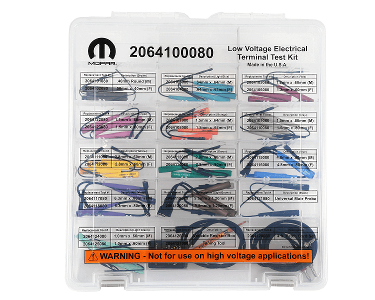
- Check the sensor ground circuit for an open/high resistance between the pressure sensor connector and the ECU connector. The circuit can be checked on of two ways. Either disconnect the ECU harness connector and measure the resistance of the sensor ground circuit. The resistance should be less than 3.0 Ohms. Or connect the (special tool #2064100080, Kit, Electrical Test Lead) to the 5-volt reference circuit and sensor ground circuit at the pressure sensor harness connector with the switch on the Electrical Test Lead Kit in the open position. With the ignition on, move the switch to the closed position. If the sensor ground is good the 5-volt reference circuit should get pulled low and set the C1440-1C fault.
- If the sensor ground circuit tested good, continue to step 3.
- If the resistance is above 3.0 Ohms or the fault doesn't set as intended, test and repair the sensor ground circuit for an open or high resistance.
- Connect the Electrical Test Lead Kit tool between the 5-volt reference circuit and the sensor signal circuit with the switch in the open position. Move the switch on the Electrical Test Lead Kit between the open and closed positions while monitoring the scan tool. If monitoring for faults, the circuit low fault should set when switched to the open position and the circuit high fault should set when switched to the closed position. If the sensor voltage is available on the scan tool, monitor the voltage readings. The voltage should be 0.0 volts when switched to the open position and 5.0 volts when switched to the closed position. Move the switch to adjust and use the tool to vary the resistance while monitoring the ECU signal voltage on the scan tool. Pick the result from a, b, or c below that best matches the results.
- If the faults set as described and the signal voltage is 0.0 volts (open) and 5.0 volts (closed) - the ECU and sensor circuits are testing good. The sensor is most likely faulty or has a poor connection at the harness connector. Check the sensor harness connector for pushed out, spread, corroded or dirty terminals before condemning the sensor.
- If the signal voltage is stuck low or only the circuit low fault sets
- the most likely cause is the sensor signal circuit is open or shorted to chassis ground. Disconnect the ECU harness connector and check the sensor signal circuit for a short to ground, or to the sensor ground circuit. If there is continuity between the sensor signal circuit and either chassis ground or the sensor ground circuit, repair the short. If the signal circuit is not shorted, continue testing for an open below.
- If the signal reading voltage was 0.0 volts on the scan tool when switched to closed it would indicate an open circuit. If voltage was present, but less than 5.0 volts it would indicate that there is likely resistance in the circuitry. Check the signal circuit resistance between the sensor harness connector and the ECU harness connector. Typically, it should be less than 3.0 Ohms. If the resistance is not below 3.0 Ohms, use the wiring information to check all related harness connectors in the system for pushed out, spread, corroded or dirty terminals before condemning an ECU. If no issues are found, the ECU is most likely faulty.
- If the signal voltage is stuck high or only the circuit high fault sets - the most likely cause is a short to voltage in the sensor signal or the sensor signal is shorted to the 5-volt reference circuit.
TYPICAL PRESSURE SENSOR CIRCUIT LOW DIAGNOSTICS:
- Disconnect the pressure sensor harness connector at the RDM. Turn the ignition on and measure the voltage on the 5-Volt reference circuit. The voltage should read between 4.93 and 5.07 volts.
- If the voltage is correct, continue to step 3.
- If the voltage is reading near battery voltage, repair the 5-volt reference circuit for a short to battery voltage. A short to battery will typically occur from a wire to wire short or due to the voltage arcing across circuits in a connector.
- If the voltage is low, continue to step 2.
- Turn the ignition off. Disconnect the DTCM harness connector to isolate the circuit. Check the 5-volt supply circuit for an open and short to ground.
- If the circuit is not open or shorted, and no voltage was present, replace the DTCM in accordance with the service information.
- If an open or short to ground was detected, repair the circuit and retest.
- Check the sensor ground circuit for an open/high resistance between the pressure sensor connector and the ECU connector. The circuit can be checked one of two ways. Either disconnect the ECU harness connector and measure the resistance of the sensor ground circuit. The resistance should be less than 3.0 Ohms. Or connect the (special tool #2064100080, Kit, Electrical Test Lead) to the 5-volt reference circuit and sensor ground circuit at the pressure sensor harness connector with the switch on the Electrical Test Lead Kit in the open position. With the ignition on, move the switch to the closed position. If the sensor ground is good the 5-volt reference circuit should get pulled low and set the C1440-1C fault.
- If the sensor ground circuit tested good, continue to step 3.
- If the resistance is above 3.0 Ohms or the fault doesn't set as intended, test and repair the sensor ground circuit for an open or high resistance.
- Disconnect the ECU harness connector. Measure the resistance of the sensor signal circuit between the sensor harness connector and the ECU harness connector. The resistance should be less than 3.0 Ohms.
- If the sensor signal circuit tested good, continue to step 4.
- If the resistance is above 3.0 Ohms test and repair the sensor signal circuit for an open or high resistance.
- Verify that the ECU is capable of detecting the correct fault. Connect all ECU harness connectors. Turn the ignition on and clear all DTCs. Connect a fused jumper, or the Electrical Test Kit tool between the sensor signal circuit and the 5-volt reference circuit at the pressure sensor harness connector. The Electrical Test Kit tool should be switched to closed to connect the circuits. The C1440-12 Transfer Case Clutch circuit high fault should set with the jumper in place.
- If the sensor circuit high fault sets with the jumper in place, replace the RDM pressure sensor in accordance with the service information. Verify the RDM fluid level is correct and perform the system bleeding procedure.
- If the sensor circuit high fault does not set with the jumper in place, use the wiring information to check all related harness connectors in the system for pushed out, spread, corroded or dirty terminals before condemning an ECU. If no issues are found, the ECU is most likely faulty.
TYPICAL PRESSURE SENSOR CIRCUIT HIGH DIAGNOSTICS:
- Disconnect the pressure sensor harness connector at the RDM. Turn the ignition on and measure the voltage on the sensor signal circuit. There should be no voltage present with the harness connector unplugged.
- If the voltage is not present, continue to step 2.
- If the voltage is present, test and repair the sensor signal for a short to the 5-volt reference circuit or battery voltage. A short to battery will typically occur from a wire to wire short or due to the voltage arcing across circuits in a connector.
- Verify that the ECU is capable of detecting the correct fault. Connect all ECU harness connectors. Turn the ignition on and clear all DTCs. Connect a fused jumper, or the Electrical Test Kit tool between the sensor signal circuit and the sensor ground circuit at the pressure sensor harness connector. The Electrical Test Kit tool should be switched to closed to connect the circuits. The C1440-11 Transfer Case Clutch circuit low fault should set with the jumper in place.
- If the sensor circuit low fault sets with the jumper in place, replace the RDM pressure sensor in accordance with the service information. Verify the RDM fluid level is correct and perform the system bleeding procedure.
- If the sensor circuit low fault does not set with the jumper in place, the ECU is most likely faulty.