BELLHOUSING Installation
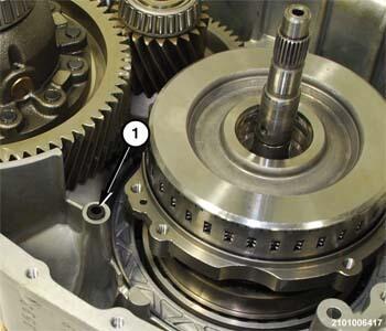
- Install a NEW
seal (1) in the port in the transmission housing.
- Install a NEW gasket (1) on the sealing surface of the transmission housing (2).
- If necessary, replace the output seal and the impeller hub seal.
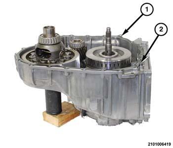
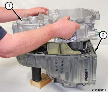
- Guide the bellhousing (1) downward over the input and output shafts and onto the transmission housing (2).
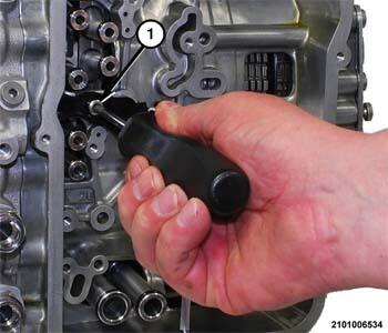
- Rotate the output gear clockwise to assure guide pin (1) alignment.
- Rotate the output gear support (1) through the window (2) behind the valve body until the guide pin engages the receptacle hole in the bellhousing.
- Engage the guide pins in the transmission housing into the receptacle holes in the bellhousing to assure proper alignment.
- Install several bolts to hold the bell housing to the transmission housing. Tighten the bolts hand tight.
- Position the transmission on the bench with the bellhousing facing outward.
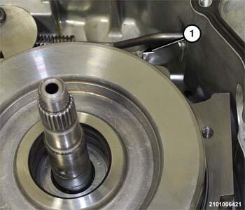
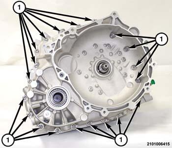
- Install the bolts (1) with NEW
seal washers to hold the bellhousing to the output gear support and tighten to the proper torque specifications. Refer to TECHNICAL SPECIFICATIONS .
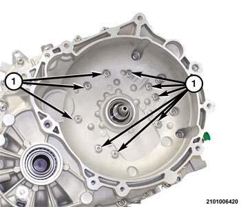
- Install the bolts (1) to hold the bellhousing to the transmission housing and tighten to the proper torque specifications. Refer to TECHNICAL SPECIFICATIONS .
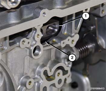
- Install NEW O-rings on both ends of the fluid transfer tubes.
- Install the fluid adapter tubes (1) in the transmission housing.
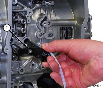
- Insert the speed sensors (1) into the transmission with the wire harness connected.
- Install the speed sensor screw (1) to hold the speed sensors to the transmission housing and tighten to the proper torque specifications. Refer to TECHNICAL SPECIFICATIONS .
- Place the Transmission Range Sensor (TRS) (1) in position on the transmission with the wire harness connected.
- Install the TRS screw (1) to hold the TRS to the transmission housing and tighten to the proper torque specifications. Refer to TECHNICAL SPECIFICATIONS .
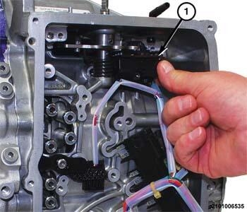
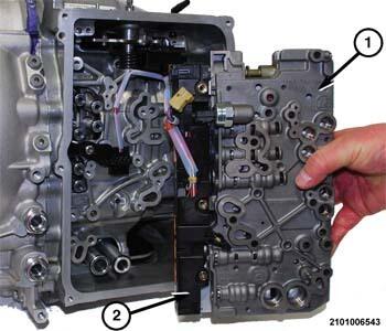
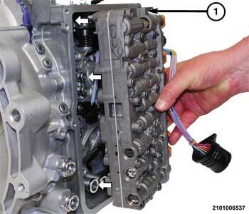
- Place the valve body (1) in position on the transmission.
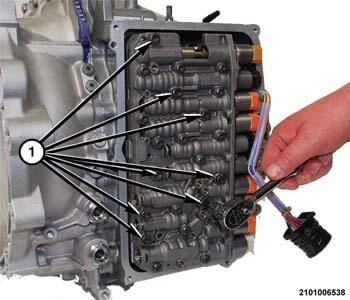
- Place the transmission solenoid wire harness connector (2) in position on the solenoids.
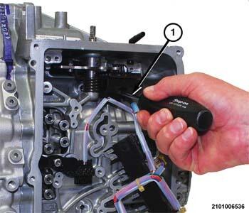
- Press the transmission solenoid wire harness connector (2) inward to engage the terminals on the solenoids.
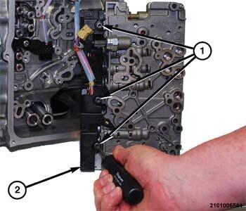
- Install the screws (1) to hold the transmission solenoid wire harness connector (2) to the valve body and solenoids and tighten to the proper torque specifications. Refer to TECHNICAL SPECIFICATIONS .
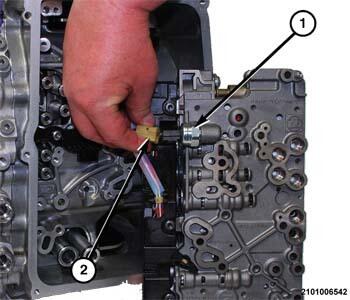
- Connect the wire harness connector (2) to the fluid pressure transducer (1).
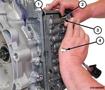
- Turn the valve body (1) over and align with the fluid transfer tubes.
- Guide the park lock valve (2) into the slot (3) on the manual valve.
- Firmly press (4) the valve body (1) inward until the O-rings on the fluid transfer adapters engage into receptacle holes on the valve body.
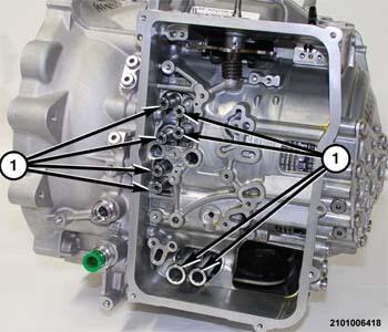
- Install the valve body bolts (1) to hold the valve body to the transmission housing and tighten to the proper torque specifications. Refer to TECHNICAL SPECIFICATIONS .NOTE:
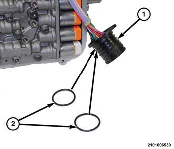
A light coating of assembly lube can be applied to the O-ring seals (2) of the transmission solenoid connector to ease installation.
- Install NEW
O-ring seals (2) on the transmission solenoid connector (1).
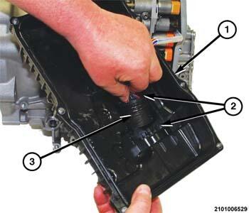
- Place the valve body cover pan (1) in position on the transmission.NOTE:
Be certain that the flat side (2) on the transmission solenoid connector (3) is aligned with the flat spot on the valve body cover pan (1).
- Insert the transmission solenoid connector (3) into the opening on the inside of valve body cover pan (1).
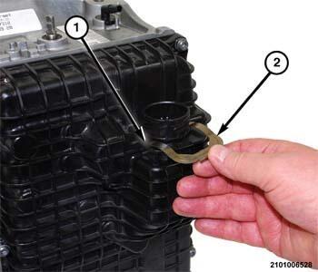
- Press the transmission solenoid connector inward until the retainer clip groove (1) is exposed on the outside of the valve body cover pan.
- Install the clip (2) to hold the transmission solenoid connector in the valve body cover pan.
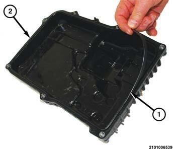
- Install a NEW
gasket seal (1) in the groove around the sealing surface of the valve body cover pan (2).
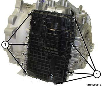
- Install the valve body cover pan and valve body cover pan bolts (1) to hold the valve body cover pan to the transmission housing and tighten to the proper torque specifications. Refer to TECHNICAL SPECIFICATIONS .
- Install the transmission in the vehicle. Refer to REMOVAL AND INSTALLATION .